Exercises - state estimation and sensor fusion
✎Modified 2020-11-16 by Aleksandar Petrov
Build your own localization system through sensor fusion and the Apriltag library
In this exercise you will learn how to create estimators with both proprioceptive and exteroceptive sensors and how to manipulate the frame transformations tree to easily fuse these estimates.
Understand how to build a TF tree in ROS and visualize it in RViz.
Be able to create a multi-package Dockerized ROS workspace, and deploy it on the Duckiebot.
Experience with working with ROS Timers and Services
Create a wheel-encoder based estimator. Understand the benefits and drawbacks of such an estimator.
Create an Apriltag-based estimator. Understand the benefits and drawbacks of this estimator.
Create a sensor fusion node that fuses estimates from the above individual estimators.
The overall goal of this exercise is to create a state estimation system that localizes the Duckiebot in global coordinates. So far we have only seen how this can be done locally, relative to the lane. This has two major limitations. First, we don’t know how far we have travelled in the lane, as we only can get estimates on our lateral offset from the center of the lane. Second, we don’t know if we are in a straight or turning lane segment. In this exercise, however, we will work towards localizing the robot in a global coordinate frame.
To be able to perform such a complex task, we will have to use all sensors onboard the robot, namely the camera and the wheel encoders. We will achieve our localization goal in several incremental steps. First, we will develop an estimator using only wheel encoders. Then, we will develop an estimator using only camera information via the Apriltag detection library. Finally, we will fuse these estimates so that we get the best of both worlds.
Encoder localization package
✎The first package you’ll create in your Dockerized ROS workspace is one that will contain a node that publishes a TransformStamped message at 30Hz with the following fields:
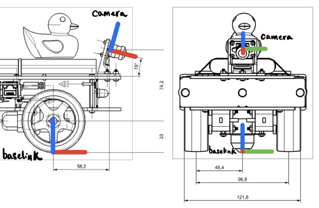
frame_id:map;child_frame_id:encoder_baselink;stamp: timestamp of the last wheel encoder tick;transform: a 2D pose of the robot baselink (see Figure 4.2 for a definition of this frame).
The node will also have to broadcast the TF map-encoder_baselink.
Deliverables:
-
A screen recording similar to this Figure 4.1 where you drive the robot in a loop and try to “close the loop” (by driving to the point where you started from). Make sure that the video contains the camera images as well as the TF tree in Rviz. Use a visible landmark as the origin of the map frame.
-
A link to a Github repository containing a package called
encoder_localization.
Hints:
-
For the estimates to be in a global frame, you will have to provide an initial pose estimate.
-
Use
tf.TransformBroadcaster()to broadcast a TF which can be visualized in RViz. Note that you can pass the exact same message as the one that your publisher uses. -
For the kinematic model of the Duckiebot, you’ll have to load the following parameters from the kinematics calibration file:
baseline,radius. -
To open RViz, simply run
dts start_gui_tools hostname.localand runrvizfrom inside the container. Note that if you keep the container running you can save your RViz configuration file so that when you reopen it, it automatically displays your topics of interest. -
Rviz uses the following color-code convention for frame axes: red for the x-axis, green for the y-axis, and blue for the z-axis.
-
To publish messages at a fixed frequency, consider using a ROS Timer. It works very similar to a subscriber except for the fact that the callback get called after a fixed duration of time.
-
This link contains many useful methods from the
tflibrary that allow you to switch between representations (e.g. expressing an euler yaw angle as a quaternion).

The video is at https://vimeo.com/477772450.
As you have probably realized, some of the advantages of this localization system is that as long as the robot is moving, the wheel encoders will provide information about the state of the robot, at a high rate and with little delay. However, the pose of the robot is an integration of the wheel encoder measurements, meaning that it is subject to drift as any inaccuracies in measurement get propagated through time. When driving aggressively or through a slippery surface these inaccuracies are amplified (try this for yourself!).
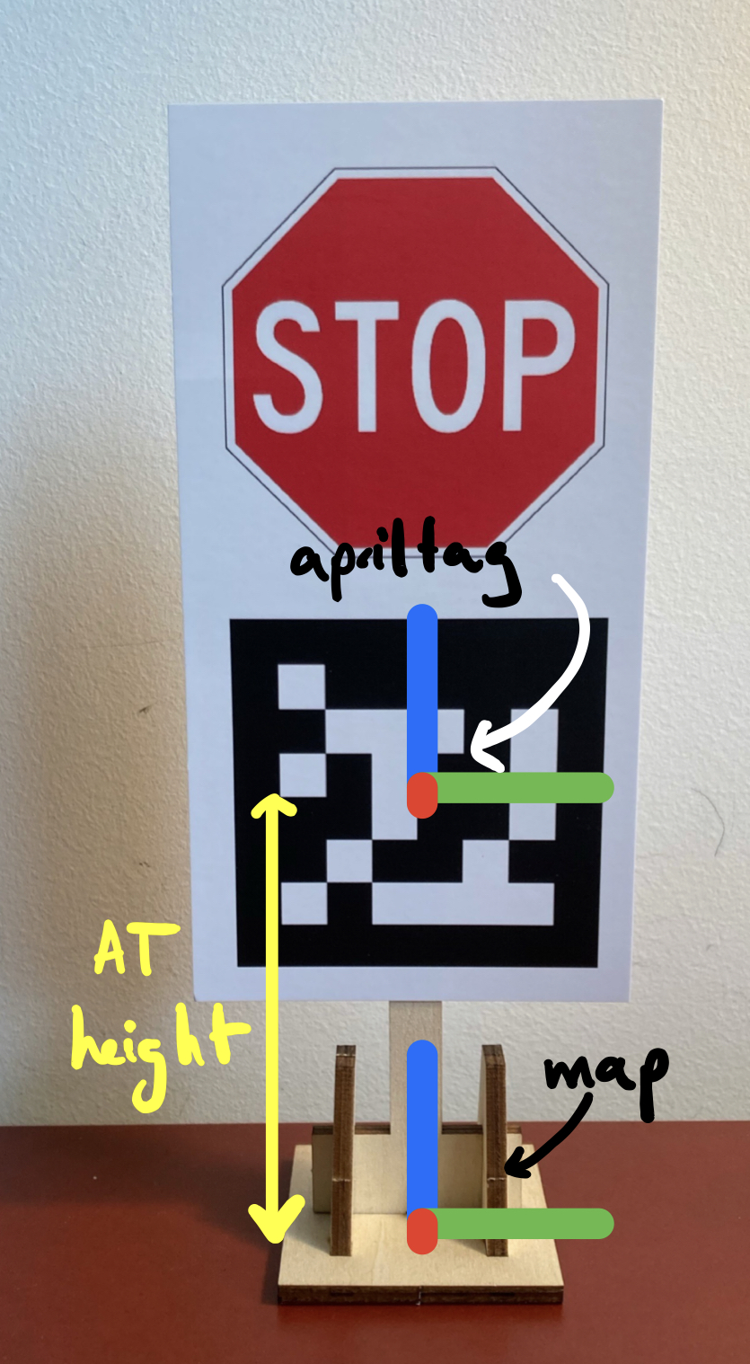
A common way of getting rid of drift in mobile robots is to either use absolute position measurements (with GPS, for instance) or to use fixed landmarks in the world as reference. This is how we humans also navigate the environment. Since there is no GPS on-board the Duckiebot, we will have to use the latter approach. This is what we will explore in the next exercise, where our landmarks will be traffic signs with Apriltags (see Figure 4.3).
Apriltag localization package
✎In this package you’ll have to place a node that subscribes to /camera_node/image/compressed and publishes a TransformStamped message (if an image with an Apriltag has been received) with the following fields:
frame_id:map;child_frame_id:at_baselink;stamp: timestamp of the last image received;transform: a 3D pose of the robot baselink (see Figure 4.2 for a definition of this frame).
This node will also have to broadcast the following TFs: map-apriltag, apriltag-camera, camera-at_baselink. Make sure that when you place the Apriltag in front of the robot you get something that looks roughly like Figure 4.5. This will make it easier to fuse this pose with the pose from the encoders.
Deliverables:
-
A screen recording similar to the one in Figure 4.6 where you move the Apriltag in front of the robot from one side of the Field-of-View (FOV) to the other. Make sure that the video contains the camera images as well as the TF tree in Rviz.
-
Instead of directly using compressed images, rectify them before passing them to the Apriltag detector. You will see that this significantly improves the accuracy of the detector but at the cost of significant delay. Provide a screen recording similar to this Figure 4.7 where you move the Apriltag in front of the robot from one side of the FOV to the other. Make sure that the video contains the camera images as well as the TF tree in Rviz. You should observe that the
mapandbaselinkare now in the same plane (or at least much closer to it than with compressed images). -
(Bonus) Offload the computation of the rectified image to the GPU of the Jetson Nano so that the improved accuracy can be obtained without significant delay.
-
A link to your Github repository containing a package called
at_localization.
Hints:
-
A frame cannot have two parents. If you try to broadcast the following TFs:
map-baselinkandcamera-baselink, you will see that you’ll only be able to see the individual frames in RViz. -
To rectify images, use the following
cv2methods:
newCameraMatrix = cv2.getOptimalNewCameraMatrix(cameraMatrix,
                                                distCoeffs,
                                                (640, 480),
                                                1.0)
cv2.initUndistortRectifyMap(cameraMatrix,
                            distCoeffs,
                            np.eye(3),
                            newCameraMatrix,
                            (640, 480),
                            cv2.CV_32FC1)
cv2.remap(compressed_image, map1, map2, cv2.INTER_LINEAR)
-
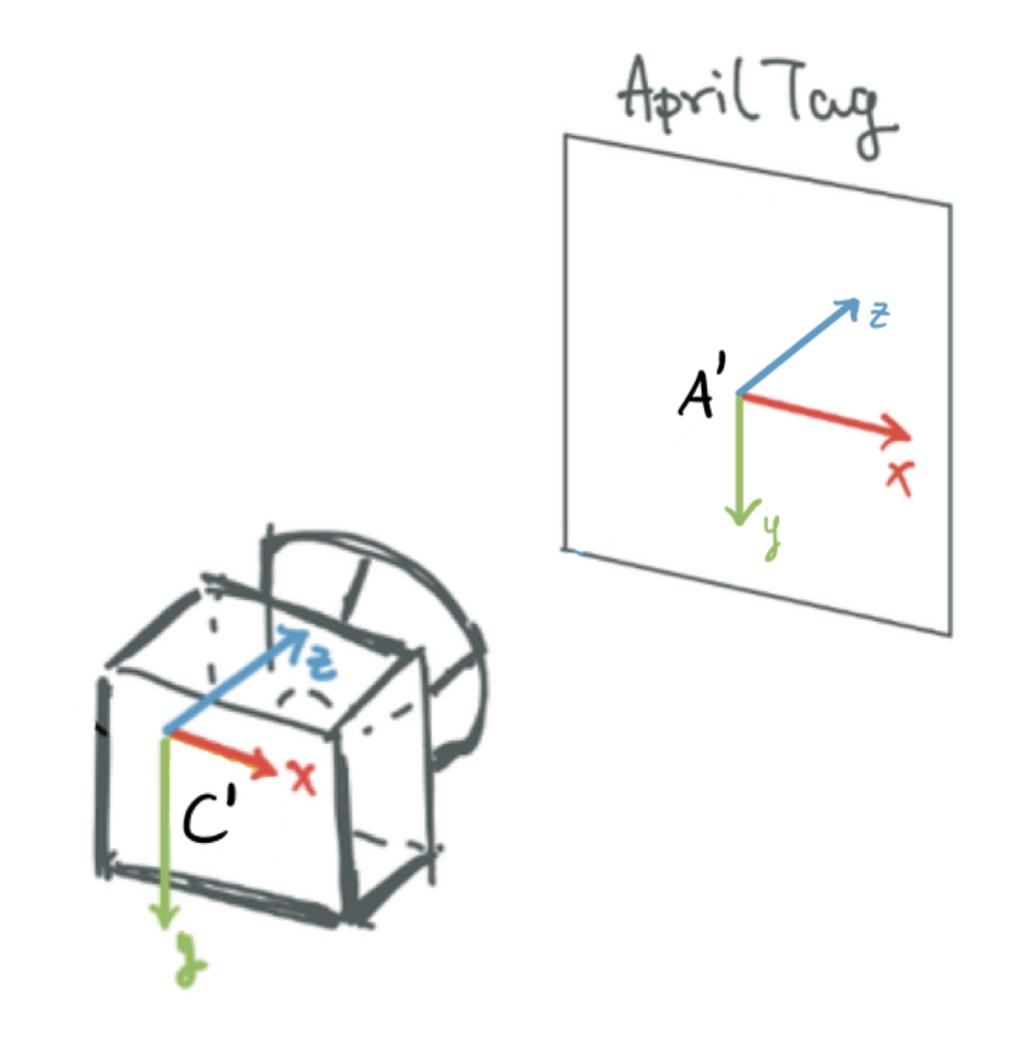
To use the Apriltag detector, consult this link. You can extract the pose of the Apriltag in the camera frame with
tag.pose_R(rotation matrix) andtag.pose_t(translation vector). Keep in mind that the coordinate frame convention (see Figure 4.4) is different than the one you are supposed to use in the deliverable! -
To broadcast static transforms, use
self.static_tf_br = tf2_ros.StaticTransformBroadcaster()
To calculate the static transform between the map and apriltag frames () use Figure 4.3 as reference. To calculate the static transform between the baselink and camera frames, you can use
Figure 4.2 as reference, or you can try to use the homography matrix obtained during extrinsic calibration.
- To convert between frames, we recommend that you use 4x4 transformation matrices. An example of such a matrix is which transforms a vector in frame B to frame A. During your manipulations, keep in mind that and for any frames and .

The video is at https://vimeo.com/477649817.

The video is at https://vimeo.com/477771555.

The video is at https://vimeo.com/477771932.
The detected Apriltag can provide accurate pose estimates with respect to landmarks but at the cost of a significant delay and a low frequency. Moreover, one cannot continuously rely on such estimates since the Apriltag could go out of sight. To combat this, we can fuse the estimates of the Apriltag and the wheel encoders for continuous, accurate and robust localization. This is the goal of the next exercise.
Fused localization package
✎In this package you’ll have to place a node that publishes a TransformStamped message with the following fields:
frame_id:map;child_frame_id:fused_baselink;stamp: current time,transform: a 2D pose of the robot baselink.
The node will also have to broadcast the TF map-fused_baselink. As a minimum, your fusion node should have the following behaviour:
-
The first time the Apriltag becomes visible, you have to calibrate the
encoder_baselinkframe/estimate to match exactly the Apriltag pose. This should be done with a ROS Service provided by andencoder_localization_node(server) whichfused_localization_node(client) can call. If you need an example of a Duckietown package that defines a similar service, check this out (pay a special attention to theCMakeLists.txtandpackage.xmlfiles). -
Publish the robot pose using the Apriltag estimate (when available) projected on the ground plane (recall that this node publishes 2D poses).
-
If the Apriltag is not visible, use the encoder estimates, starting from the last Apriltag pose received (there should be no pose jump if the Apriltag goes out of sight).
-
If the Apriltag becomes visible again, switch back to using Apriltag estimates (a jump in fused pose is allowed).
-
You don’t have to handle the delay or the variance of the individual estimates to complete the exercise, but you are more than welcome to!
Deliverables:
-
A screen recording similar to this Figure 4.8, where you drive the robot in a loop around the Apriltag with the virtual joystick. Start the recording with the Apriltag not visible, so that you validate that your calibration service is working and when it does bacome visible all the frames align. You should end the trajectory where you started it (feel free to use a marker on the ground). Make sure that the video contains the camera images as well as the TF tree in Rviz.
-
A link to a github repository containing a package called
fused_localization

The video is at https://vimeo.com/477772244.