Appearance Specifications
✎Modified 2018-12-19 by tanij
Nothing.
Knowledge of the Duckietown appearance specifications
This document describes the Duckietown appearance specification. Specifications are a set of rules for which a functional system has been verified. This means that if these rules are followed while building a Duckietown, Duckiebots will (most probably!) work.
Any Duckietown not adhering to the rules described here cannot be considered a Duckietown, and may cause the Duckiebots operating within them to fail in unexpected ways.
Small perturbations to the appearance specifications might affect negatively the performance of Duckiebots, although most algorithms are robust to variations.
Layer 1 - The Floor Layer
✎Modified 2018-12-19 by tanij
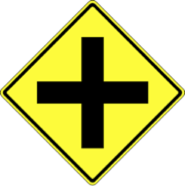
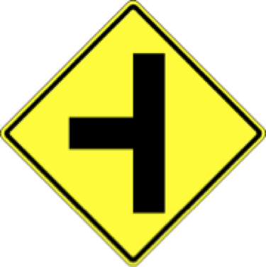
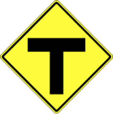
The floor layer is made of interlocking black tiles. Each tile represents one road element: straight, curve, 3-way intersection, 4-way intersection and empty tile. The road elements are positioned in specific orders to create compliant Duckietowns. The road elements are shown in Figure 2.1, note that the left turn and right turn tiles are symmetric: one is the 90 degree rotation of the other.
Each tile is square and measures 61 x 61 cm (2 ft x 2 ft) from the outer edges of the interlocking dents. The thickness of the tiles is not as important as the surface roughness. The objective is having good grip between the Duckiebots and the road in order to minimize slipping of the wheels.


The empty tiles can be of any color, although it is discouraged to use the same colors as the road markings (red, white and yellow).
For tiles to become road elements, we need to apply road markings. Road markings can be obtained through the application of tapes of different colors and sizes.
Tapes
✎Modified 2018-12-18 by tanij
There are 3 colors of tapes used in Duckietown: white, yellow, and red.
White tape
✎A Duckiebot on a road never collides with Duckiebots or other Duckietown elements if it never crosses or touches a white tape strip.
Here are some facts about the white tapes:
-
White tapes must be solid (not dashed);
-
The width of the white tape is roughly 4.8 cm (1.88 inches);
-
The white tape is always placed on the right hand side of a lane. We assume that the Duckiebots drive on the right hand side of the road.
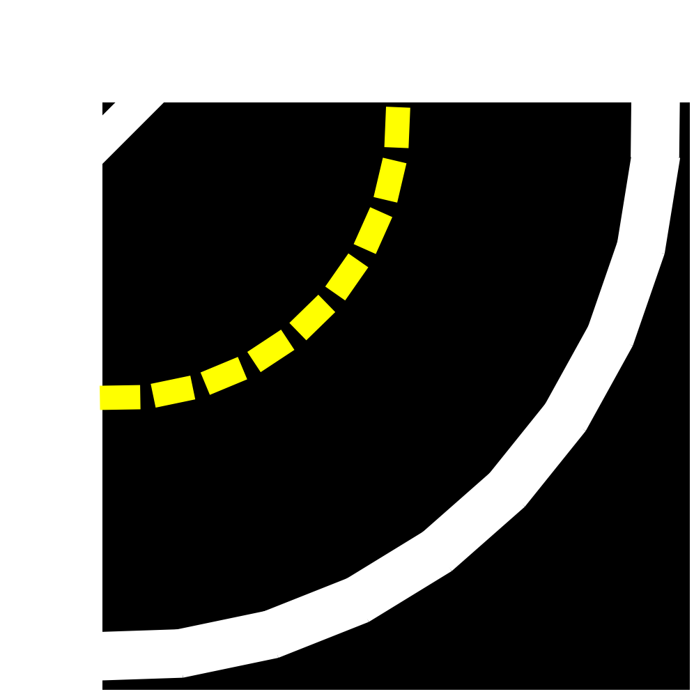
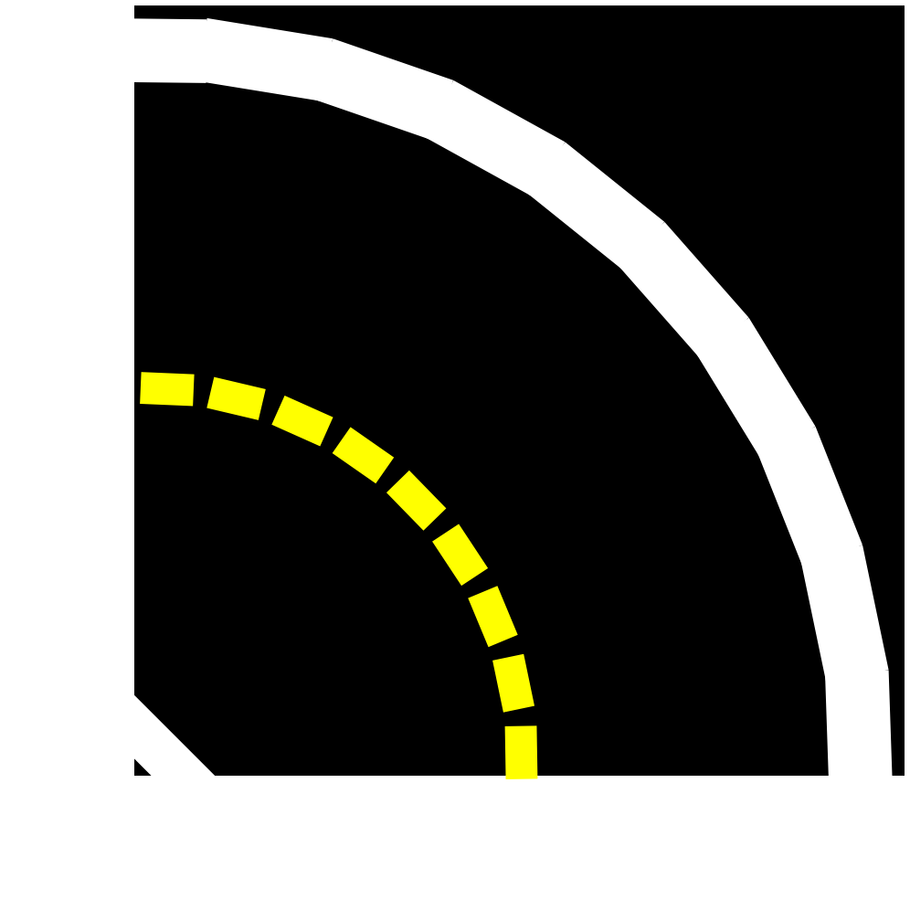
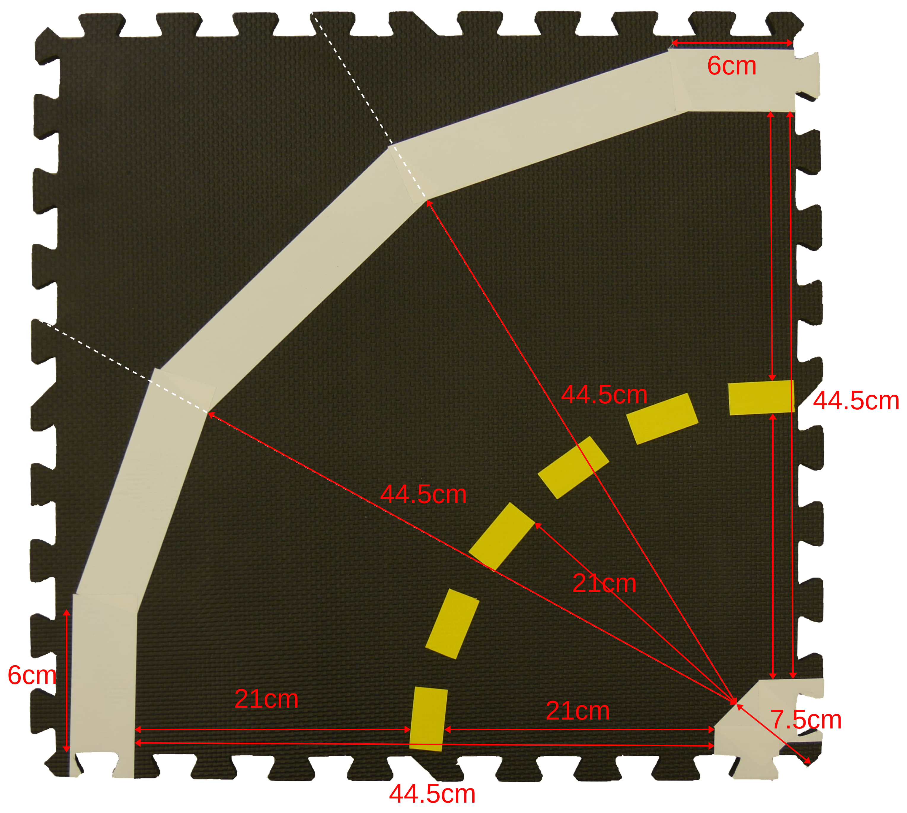
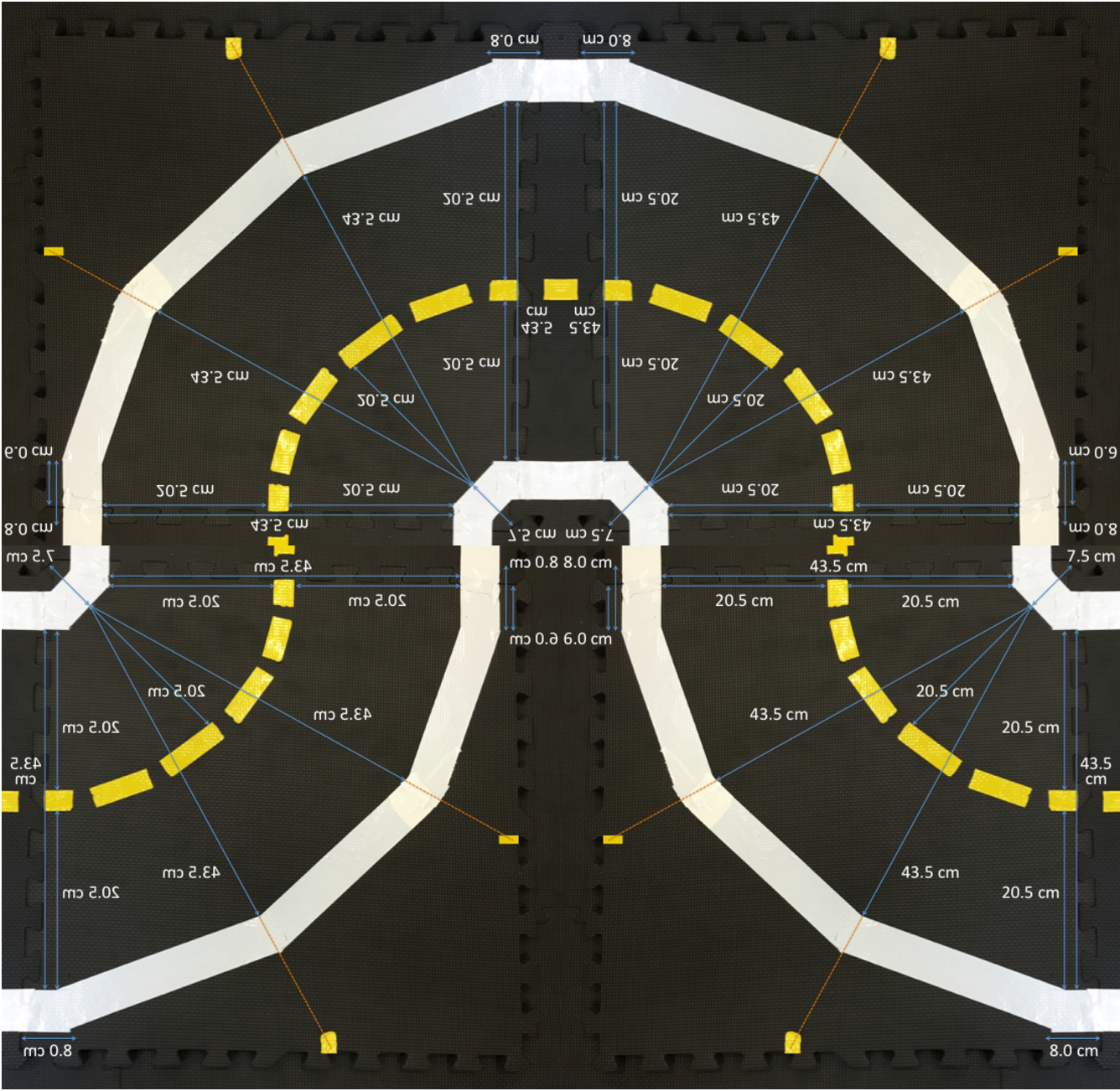
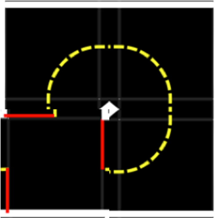
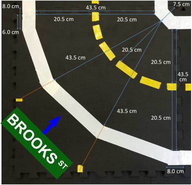
- For curved roads, the white lane marker is formed by five pieces of white tape, while the inner corner is formed by three pieces, placed according to the specifications in the image below, where the edge pieces are matched to adjacent straight or curved tiles (Figure 2.5).
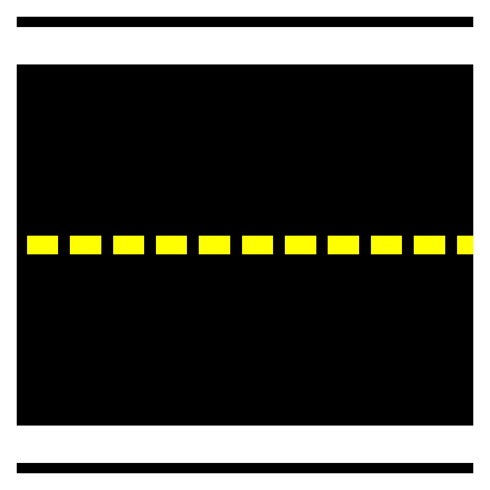
Yellow tape
✎Here are some facts about the yellow tapes:
-
Yellow tape must be dashed (not solid);
-
Each piece should be 5 cm long and placed with a 2.5 cm gap between each piece;
-
The width of the yellow tape is roughly 2.4cm (0.94 inches);
-
The yellow tape is always placed on the left hand side of a lane, i.e., in the center of the road. We assume that the Duckiebots drive on the right hand side of the road.
Yellow tapes on curves: see curved road image (Figure 2.5) in white tape section. Pieces at tile edges should be in center of lane, piece at the middle of the curve should be approximately 21 cm from middle of inner center white piece of tape, with approximated circular arc in between.
Red tape
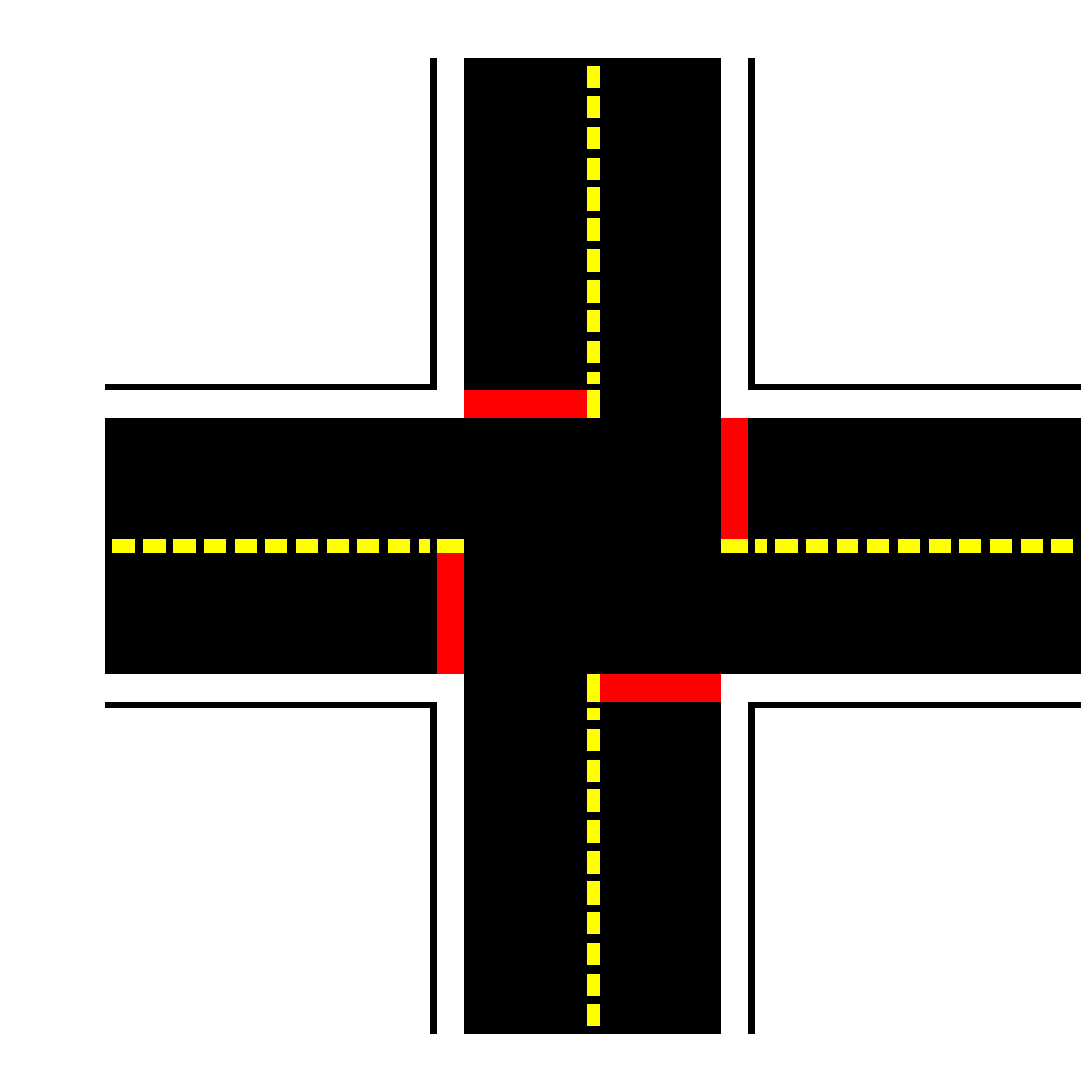
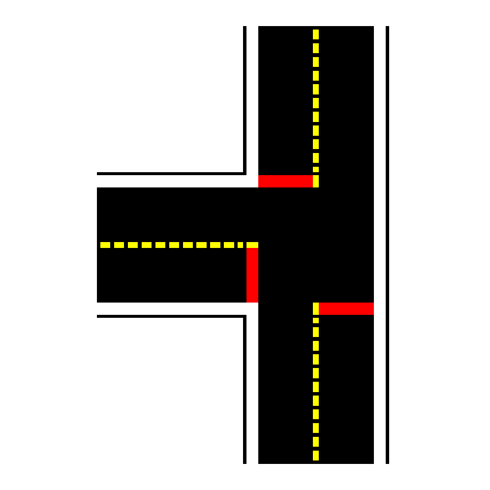
✎Red tapes MAY only appear on intersection tiles.
The width of the red tape must be the same as the white roll (roughly 4.8cm or 1.88 inches) and should cross the entire lane perpendicular to the road.
The placement of red tape should always be under yellow and white tape, as shown, e.g., in Figure 2.3 or Figure 2.4.
A Duckiebot navigates Duckietown by a sequence of:
- Navigating one or more straight tiles until a red tape appears,
- Waiting for the coordination signal,
- Executing an intersection traversal,
- Re-localizing in a straight tile.
Topological Constraints During Map Construction
✎Modified 2018-06-22 by Andrea Censi
Here are some topological rule constraints that must be met:
-
An intersection can NOT be adjacent to a curved road tile or another intersection tile.
-
Any two adjacent non-empty tiles must have a feasible path from one to the other of length two: if they are adjacent, they must be connected.
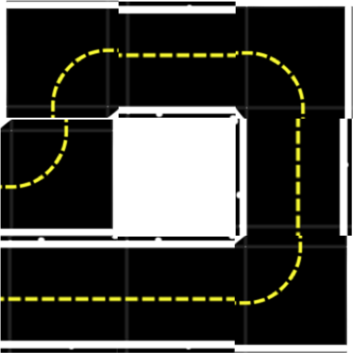
Some examples of non-conforming topologies are shown in Figure 2.6.
Parking Lots
✎Modified 2021-03-21 by tanij
The tile types described here are experimental. Use at your own risk!
A parking lot is a place for Duckiebots to go when they are tired and need a rest.
A parking lot introduces three additional tile types:
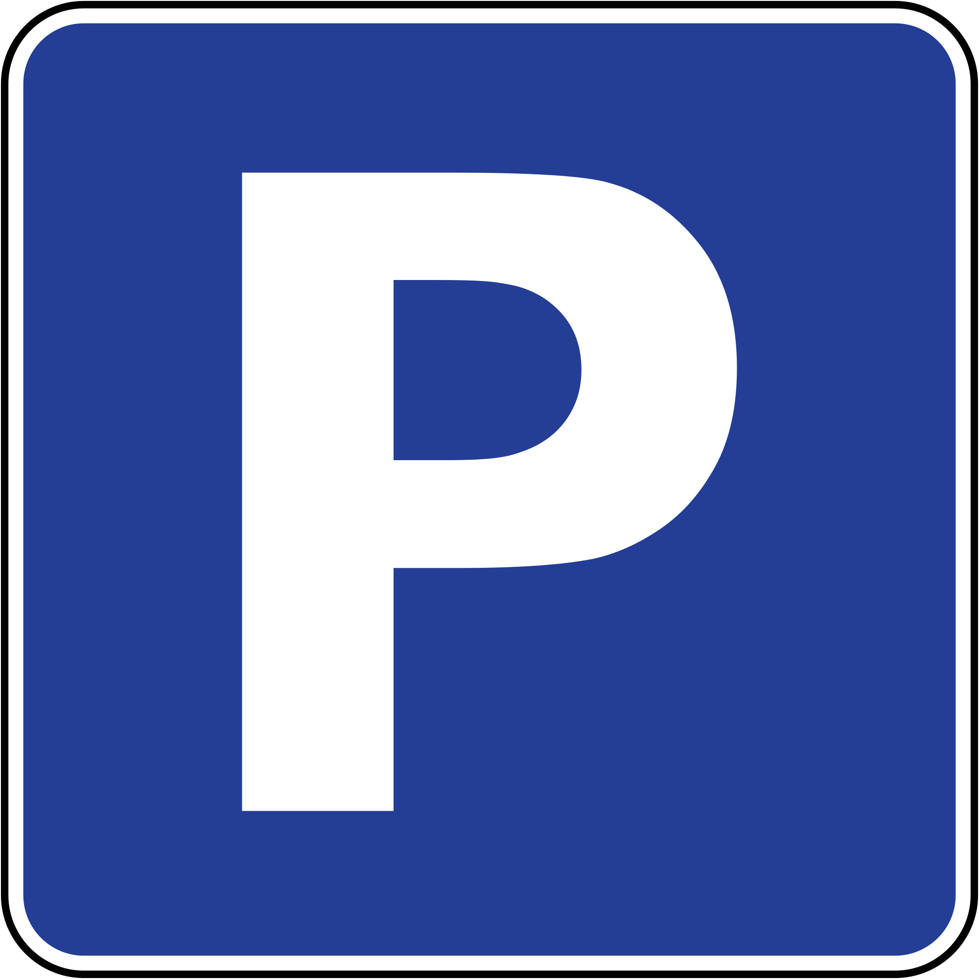
- Parking lot entry tile: This is similar to a straight tile except with a red stop in the middle. The parking lot sign (Figure 2.8o - parking) will be visible from this stop line.
- Parking spot tiles:
- Parking spot access tiles:
The following are the rules for a conforming parking lot:
- One “parking spot” has size one tile.
- From each parking spot, there is a path to go to the parking lot entry tile that does not intersect any other parking spot. (i.e. when a Duckiebot is parked, nobody will disturb it).
- From any position in any parking spot, a Duckiebot can see at least two orthogonal lines or a sign with an April tag.
Launch Tiles
✎Modified 2021-03-21 by tanij
The tile type described here is experimental. Use at your own risk!
A “launch tile” is used to introduce a new Duckiebot into a Duckietown in a controllable way. The launch file should be placed adjacent to a turn tile so that a Duckiebot may “merge” into Duckietown once the initialization procedure is complete.
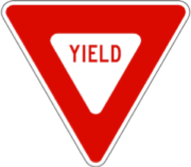
A “yield” sign should be visible from the launch tile.
Layer 2 - Signage and Lights
✎Modified 2018-12-19 by tanij
Generally, it is advisable to adhere signal layer elements to the tiles with double-sided tape. Under no circumstances should any tape be obscured by the base of the stands. At least a 0.5 cm free (black) space should separate any line from a signal layer elements’ base.
Traffic Signs
✎Modified 2021-04-17 by Abdullatif Rashdan
Traffic signage in Duckietown is obtained through the union of a traffic signs and an April Tag, as shown in Figure 2.7
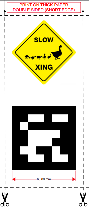
We call the symbol above traffic sign, while the code below is an AprilTag.
To print and assemble the signs refer to Unit B-2 - Traffic Signs Assembly.
Specifications
✎Modified 2021-03-21 by tanij
For traffic signage to be compliant:
- The center of the traffic signs is 13 cm height from the floor layer;
- The AprilTag is 6.5 cm sq.;
- There is a white border of roughly 0.8 cm around them;
- The signage stands perpendicular to the ground, and the angle of the sign with the road is .
- The signal is flat (no deformation / folding) and without wrinkles. This can be obtained, e.g., by printing the signs on thick paper.
Types
✎Modified 2018-12-19 by tanij
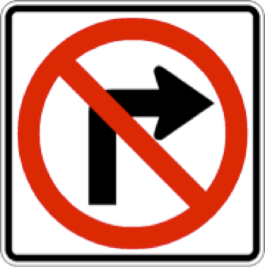
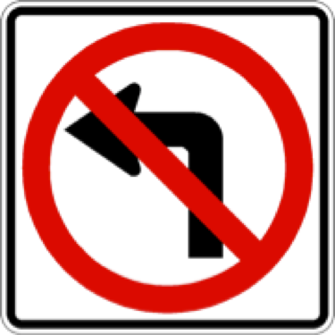
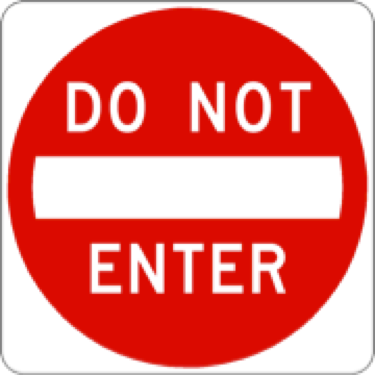
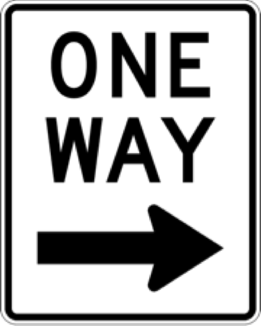
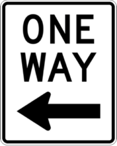
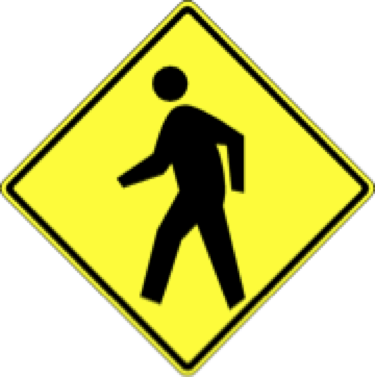
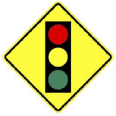
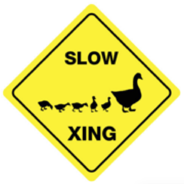
The allowable traffic signs are as in Figure 2.8.


Placement
✎Modified 2021-10-30 by tanij
Modified 2018-12-19 by tanij
Signs may appear on the opposite side and at the corner of the adjacent tile from which they are viewed. In the absence of any signs, it is assumed that all network flows are allowed so a sign MUST be placed and visible whenever this is not the case.
Signs must only be placed on empty tiles, or next to one of the other tile types if on the border of a map. As mentioned, it is important to not overlap the base of the sign stand with any road marking.
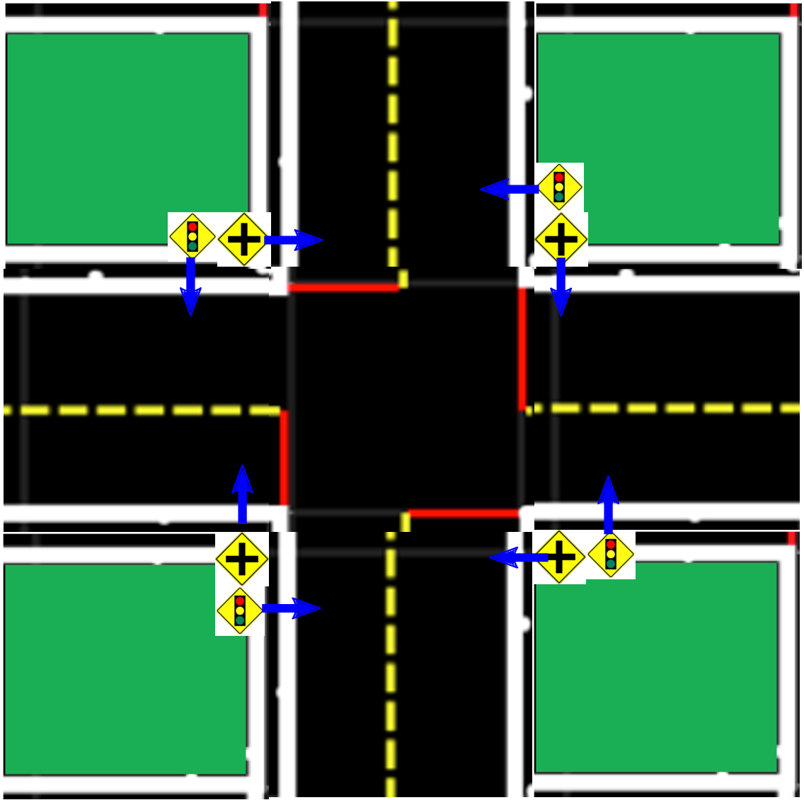
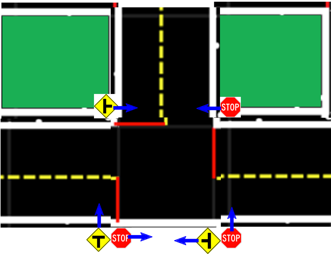
The sign placements for four different cases are shown in Figure 2.9. At intersections, from each stop line 2 signs should be clearly visible: 1) the intersection type (traffic light or stop sign) and 2) the intersection topology (3-way with correct orientation, or 4-way).
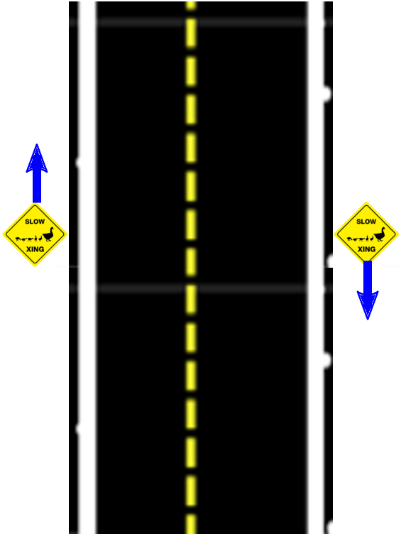
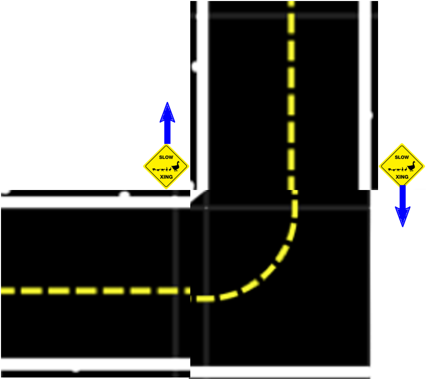
On straight and curved roads, additional signs can be added as desired. Their placement is indicated in Figure 2.9c - straight road and Figure 2.9d - curved road. The signs should be placed at the border between two tiles and should face towards oncoming traffic as indicated.
In these figures the arrow is the direction of the sign.
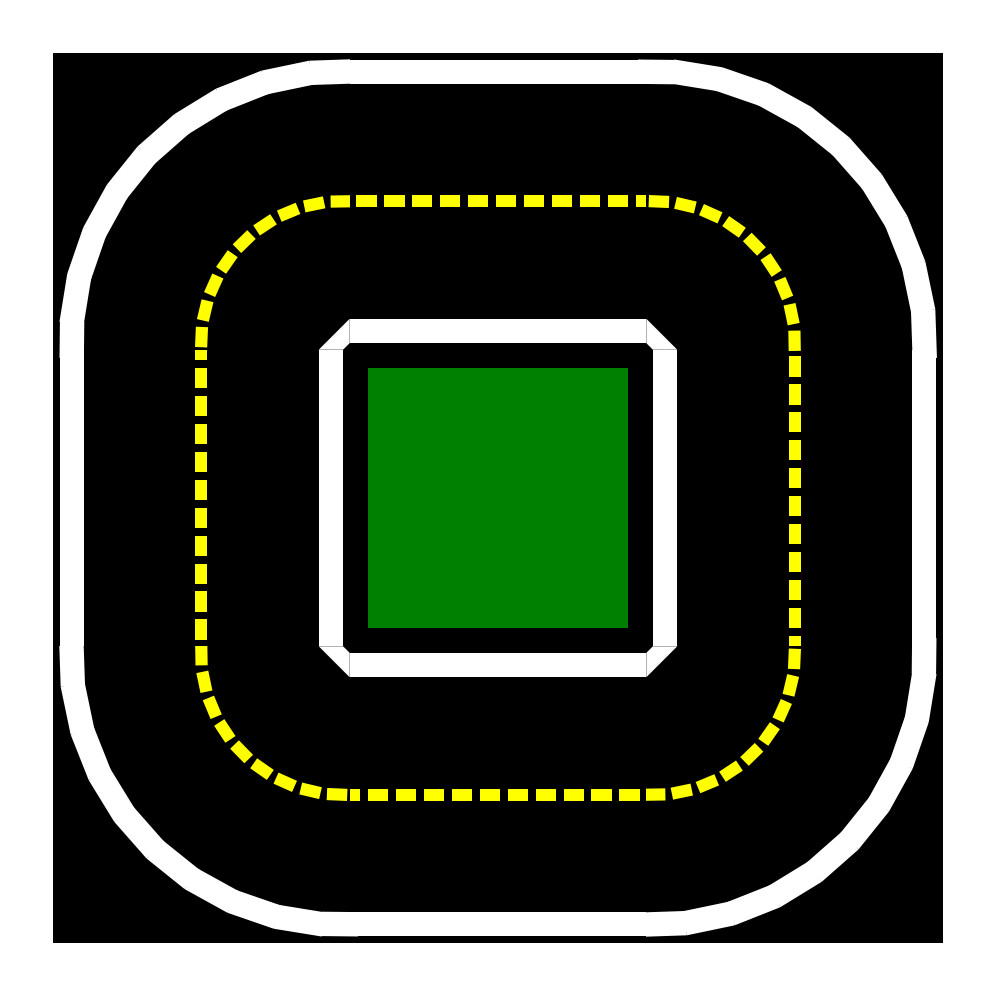
Street Name Signs
✎Modified 2018-06-22 by Andrea Censi
Specifications
✎-
Font: arial.
-
Color: white as foreground and green as background.
-
Border: no additional borders
-
The rounded corners are modified into 90 degrees.
-
Height: center of the sign height is 1.5 in. (2.1 in),
-
Width: Currently 4.5 in for id 500-511. (6.1 in +1.1 in “ST” or 5.5 in + 1.7 in “AVE”)
-
Alphabet = English upper case. Different writing systems may need different algorithms.
-
Text direction: Horizontal for alphabetical languages.
Placement
✎- Similar to traffic lights: The street name should sit on a pole that is based at the corner of the tile outside of the allowable driving region. The bottom of the street name should be at a height of 7in, and allow a Duckiebot to pass through. The street names should be visible from both sides of the road.
Every segment of road must have at least one road name sign.
Every turn tile should have a road name sign.
The placement of the road name signs is as indicated in Figure 2.10.
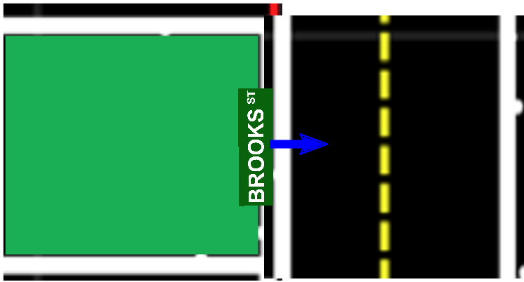
Street name signs should never be perpendicular to the road - they are too big and obtrusive.
Traffic Lights
✎Modified 2021-10-30 by tanij
The assembly procedure for building traffic lights can be found in Unit B-3 - Assembly - Traffic Light DT18-TL.
Placement
✎The lights must be at a height of 20 cm above the center of the intersection tile.
The computational stack of the traffic light should be mounted in the appropriate housing outside the allowable driving region. The cabling should be housed in the appropriate structure as detailed in Unit B-3 - Assembly - Traffic Light DT18-TL. The traffic light pillar stands should be positioned in such a way that the embedded traffic sign stands respect the above specifications for traffic light stands.
comment
this should be part of the “traffic rules” sections.