Assignment
✎Modified 2018-08-28 by Josh Roy
Translations (33 points)
✎Modified 2020-07-18 by Andrea Censi
A translation can be represented as a tuple corresponding to the
amount a point moves in each direction. Write the answers to the following
questions in answers.md.
-
The robot is at the origin, . It drives forward for 5 seconds at 2.5 meters per second. So its velocity is . How many meters has the robot driven, and what is its new position? Represent its new position as a 3-vector.
-
Assume the robot is omnidirectoral; that is it can move in any direction without turning. This means we can ignore the rotation. The robot drives at m/s for 10 s, so its velocity is . How many meters has the robot driven, and what is its new position? Represent its new position as a 3-vector.
-
To fix this problem, we add an extra entry to the position vector which is always . Position at the origin is represented with the vector:
We can represent a transformation as a matrix , where
To translate the robot, one performs the following multiplication: . Where is the position at the next timestep and is the position at the current timestep.
For this problem, the robot starts at the origin. It moves right meters in the direction, flies up in meters, and then moves backward in the direction meter (for a net transform of in ).
4.1. Draw the robot’s trajectory in three dimensions on a labeled
coordinate frame. You can draw it by hand and take a picture or
scan it, or use an image editor or drawing program. Submit this
picture as trajectory.png.
4.2. Write out the transformations as three separate transformation matrices. Write this answer in answers.md.
4.3. Multiply the matrices together to get one single transform. Write this answer in answers.md.
4.4. Multiply the matrix by the robot’s position vector to get its new location. Write this answer in answers.md.
Show all of your work
Understanding a Point Cloud (33 points)
✎Modified 2020-07-18 by Andrea Censi
The robot observes the following point cloud, denoted in the form :
For frame of reference, use is off to the robot’s right, is straight ahead, and is to the robot’s left.
For the following problems, assume this is all points the robot can see in the world, so do not worry about new things that might be out of frame.
5.1. Draw a graph with the robot at facing forward along the axis
and draw the points that the robot sees. Submit this graph as an image
titled question_5_1.png.
5.2. Now assume the robot drives forward one meter. Provide the new sensor
readings, assuming perfectly accurate sensors and a perfectly accurate
motion model. Draw them in a new version of the graph above. Submit this
graph as an image titled question_5_2.png.
5.3. Now assume the robot rotates in place from its current location
by 30 degrees (clockwise). Draw what it would see. Submit this
graph as an image titled question_5_3.png.
Robotic Arms (33 points)
✎Modified 2020-07-18 by Andrea Censi
A 2D linear robot has three joints as depicted below. The distance between the first and second joint is 3m, the second and third is 5m, and the third and end is 2m.
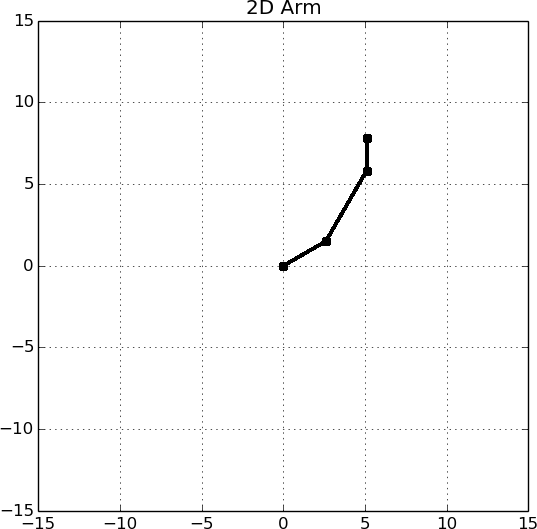
6.1. Implement the transformations in the skeleton code (provided in the GitHub Classroom), so that the arm joints move correctly and the base transformations are drawn. After you have implemented the transforms correctly, you should be able to see the arm’s state as shown in the example image below. You should be able to move joint one forward and backward with ‘i’ and ‘k’, and joint two forward and backward with ‘j’ and ‘l’ and joint three forward and backward with ‘a’ and ‘d’ and see the arm update its state. We recommend drawing the trigonometry out on paper before implementing! When the joint angles are , the arm should be pointed horizontally along the X axis.
6.2. Where is the arm when the joint angles are ? Give the position of each joint in the base coordinate system.
6.3. Provide joint angles that result in the end effector of the arm being at location .
6.4. Is the positioning in question 6.3. possible in real life? Why or why not?
Handin
✎Modified 2020-12-07 by sageshoyu
When you are done, use this link to create your Transforms GitHub Repo. Commit and push the relevant files:
- arm.py
- answers.md
- trajectory.png
- question_5_1.png
- question_5_2.png
- question_5_3.png