Charging module
✎Modified 2019-09-24 by hosnerm
For the construction of a charging module, you have many degrees of freedom. This includes the choice of material of the wooden structure (may be metal as well), the type of connection between the structure elements (screws, glue, nails), the length of the cables and many more.
However, the following requirements need to be satisfied:
- Insulators need to be mounted above tiles (Figure 4.4) for optimal pressure between current collector and charging rails
- Insulators need to be centered with respect to a lane to obtain good contact in center of lane
- There must be at least in between the white lines and the pylons to provide enough space to drive in a lane
- Enough high voltge poles (one per tile) must be used to provide a stable charger
In the following, you find the description on how we did it in Zurich.
Material for one charging module Section 4.1 - Material for one charging module
Extra tools for assembling Section 4.2 - Extra tools
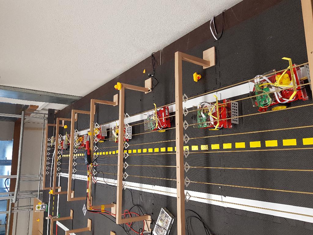
A charging module for charging Duckiebots Figure 4.1.
Material for one charging module
✎Modified 2018-09-01 by ThomasAckermann
In this list, will denote the number of charging rail tiles in a charging module. Reminder: One charging rail tile can fit Duckiebots ( per lane).
- brass rod , length ()
- wooden structure top piece ()
- wooden structure side piece ()
- wooden structure floor piece ()
- woodscrew for high voltage pole, i.e. screw
- screw and nuts
- insulator - self-print here or order here
- Drill and
- power supply which enables you to drive 5V and 30Amps
- power cable
- cable-end-sleeve
- cable shoes M4
- M4 screw 10mm and M4 Nut
- red cable
- black cable
- laboratory plug CAT I Ø4mm
Extra tools
✎Modified 2018-09-01 by ThomasAckermann
In order to put things together you may need the following extra tools:
- crimping tool
- wire stripper
- hot glue gun
- solder iron and solder
- drill
- screw driver
Building a charging module
✎Modified 2018-08-22 by Julien Kindle
Assemble the wooden structure
✎Modified 2018-08-23 by Julien Kindle
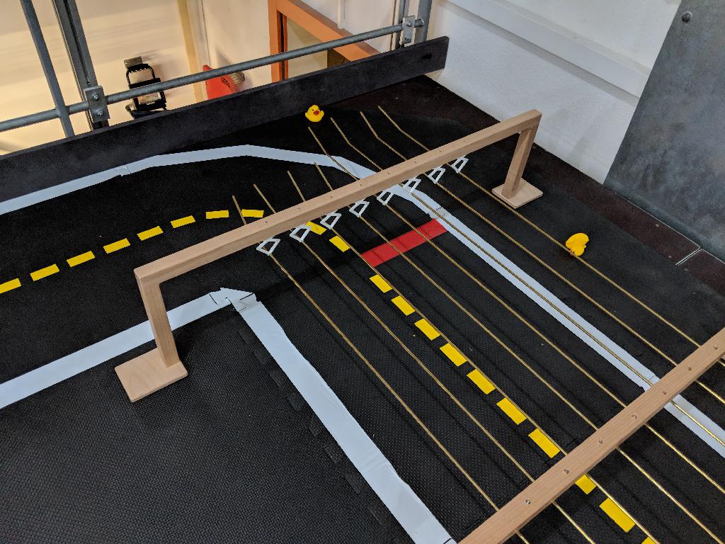
Assemble the wooden structure as in Figure 4.2. This part may differ from our reference part. The important and neccessary specifications are: (i) the structure must be larger than one tile such that a road (with margins on both sides) may fit underneath and (ii) the space between the tile and the bottom part of the crossbar must be exactly 21cm (see Figure 4.4).

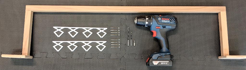
Prepare for mounting the insulators
✎Modified 2018-08-23 by Julien Kindle
Make sure you have the parts ready seen in Figure 4.3.
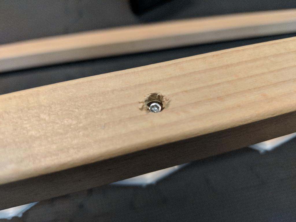
Drill the holes
✎Modified 2018-08-23 by Julien Kindle
Drill 3mm holes such that the insulators will be centered after mounting, seen in Figure 4.4

The 6mm holes (depth roughly 5mm) are optional and act as a hideout for the screw heads. The resulting holes should look like Figure 4.5.

Mount the insulator
✎Modified 2018-08-23 by Julien Kindle
Mount the insulator 3D prints as seen in Figure 4.6 and Figure 4.7.

Fix the high voltage poles to tiles
✎Modified 2018-08-31 by ThomasAckermann
Use double-sided tape to mount the high voltage poles to the tiles (Figure 4.8). Make sure that the high voltage poles are aligned throughout the whole charging module.
Optional: you could also use hot glue instead of double-sided tape.
Bend brass rails and mount them
✎Modified 2018-08-24 by Julien Kindle
Bend the charging rails 5cm on both sides (in the same direction) to ensure that Duckiebots do not get stuck when arriving at the charging rail tiles (Figure 4.8).
Then, clip the brass rails into the insulators.
Solder laboratory plugs
✎Modified 2018-08-25 by ThomasAckermann
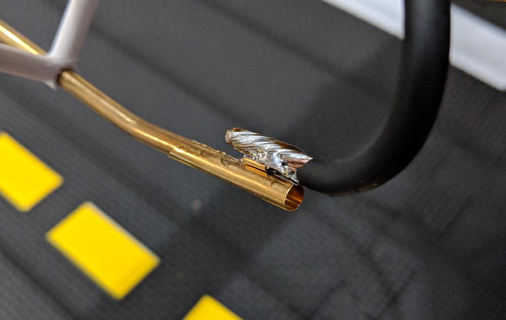
Strip the insulation of the four red and four black cables on both sides with a wire stripper off. Then solder four red and four black cables each to a laboratory plug as seen in Figure 4.9. These cables should be approximately 20-25cm long.

Attach cable shoes
✎Modified 2018-08-31 by ThomasAckermann
In order to crimp a cable shoe onto a cable, you need the following things which you can see in Figure 4.10.

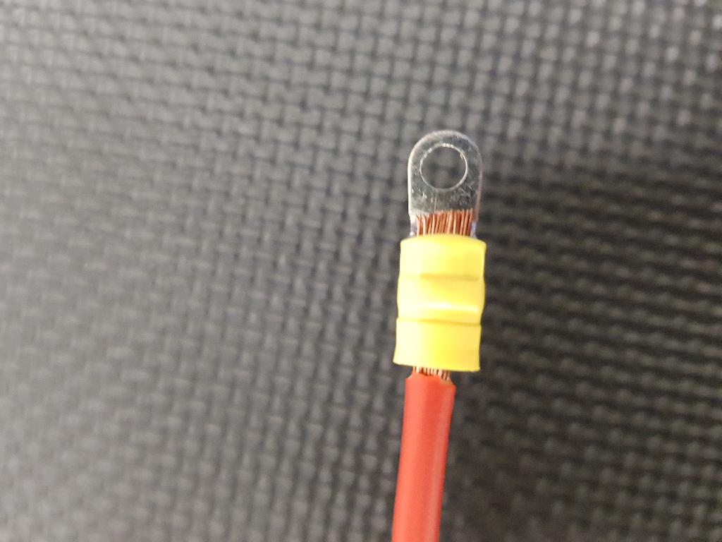
First put the cable shoe onto the uninsulated cable such that it looks as in Figure 4.11. Then take the crimping tool, put the cable inside the yellow hole and press the cable shoe on it.
Connect the cable to the power supply
✎Modified 2018-08-31 by ThomasAckermann
Mount a cable shoe with a crimping tool on the other side of these cables you have soldered. Then connect two red and two black cables respectively together with another cable shoe with a M4 screw and a M4 nut as seen in Figure 4.12. Then connect to the third cable shoe the corresponding red/black cable which will go towards the power supply. This third cable should be long enough to reach the power supply. Also attach to the end of the third cable a cable shoe.
Plug the soldered laboratory plug cable to the brass rail
✎Modified 2018-08-25 by ThomasAckermann
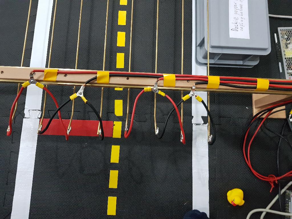
Connect the laboratory plugs to the bended ends of the charging rails as seen in Figure 4.13. The cables of the brass rods must be polarized as seen in Figure 4.14. Make sure that you connect the four rods on the left to one power supply and another four rods on the right to the other power supply.

Prepare the power cable for the power supply
✎Modified 2018-08-31 by ThomasAckermann
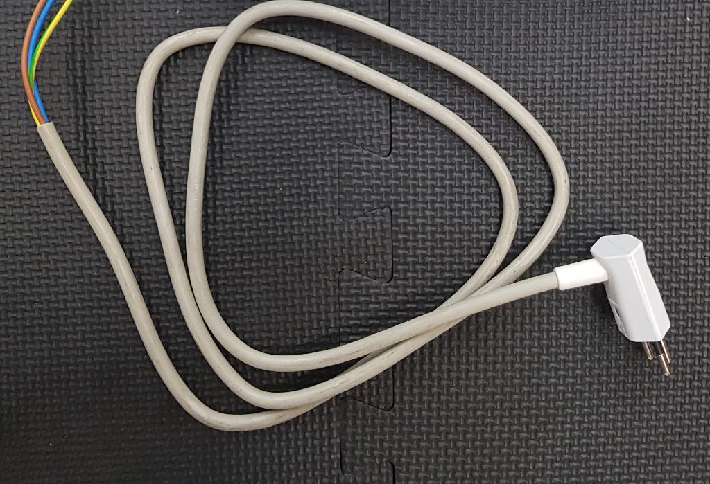
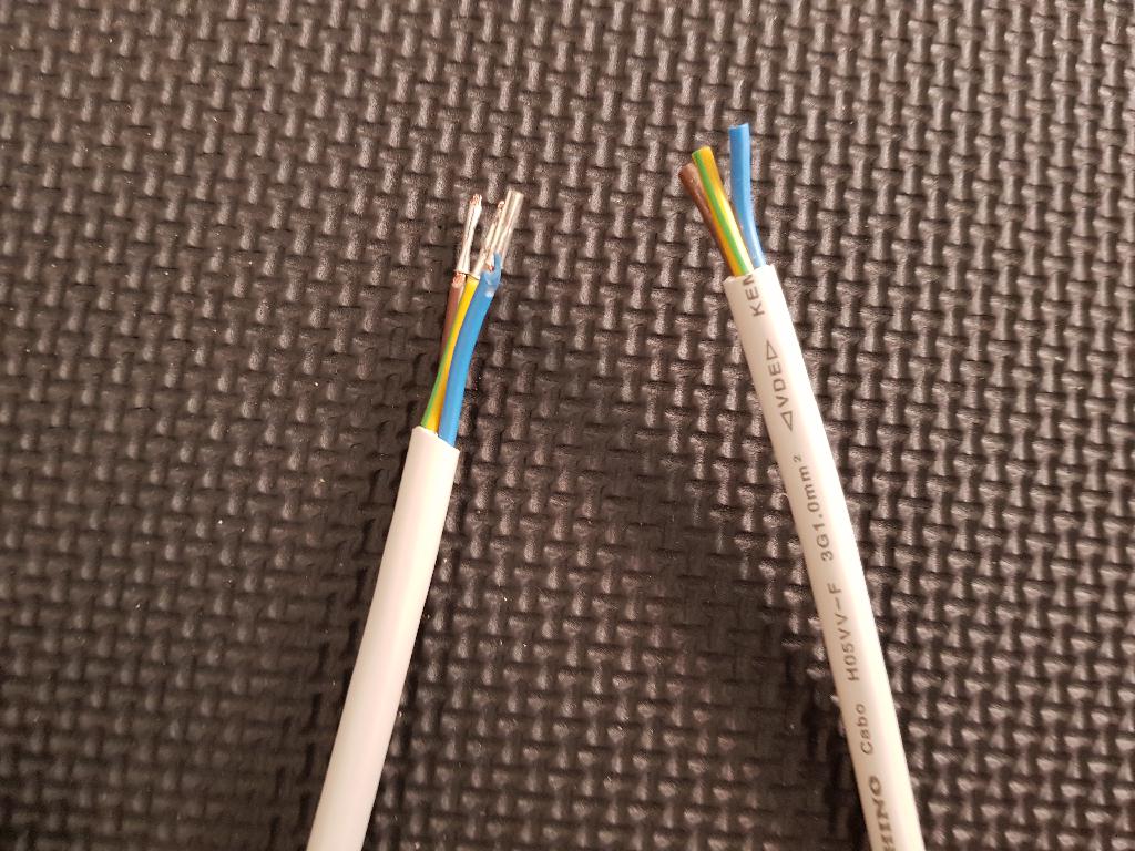
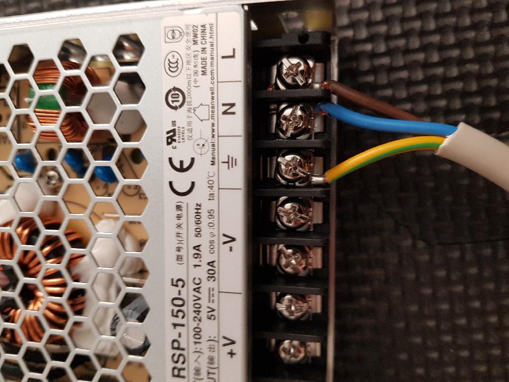
Take the power cable Figure 4.15 and strip the isolation off. Then attach a cable-end-sleeve with the crimping tool as seen in Figure 4.16. Then connect the prepared cable to the power supply exactly as it is shown in Figure 4.17.
Note: It is important that ground, phase and neutral phase is connected the right way, so the colors need to match.
Attach to power source
✎Modified 2018-08-31 by ThomasAckermann
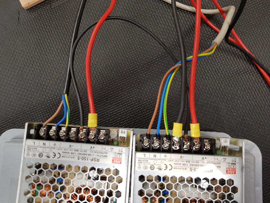
Connect the power supply to the rails. Red cable to V+ and black cable to V- as shown in Figure 4.18. Make also a connection between the two power supplies ground, in order to have a common ground.
Adjust the output voltage of the power source
✎Modified 2018-08-31 by ThomasAckermann
Turn on the power supply by plugging in the power cable. There is a voltage regulator - the plastic screw - (see Figure 4.18) next to the V+ connection - there you can adjust the voltage. Take a screw driver and a multimeter and measure the Voltage across V+ and V-. The Voltage should be adjusted to 5.5V.
Test your setup
✎Modified 2018-08-31 by ThomasAckermann
Place an assemblied Duckiebot Figure 1.17 which is capable of charging underneath the charging rails, turn on the power supplies and see if the battery is going to charge.