Autobot specifications and assembly
✎Modified 2020-01-20 by AmaurX
Fantastic Autobots and how to build them : upgrade your Duckiebot to become an Autobot
additional hardware depending on configuration
a Autobot ready to be detected by the localization system
Flashing the autobots
✎Modified 2019-09-24 by hosnerm
For a functional autolab, we strongly recommend using hostnames of the type :
- autobotXX (with XX starting at 01)
The autobot part can be changed, but the numbers at the end make the whole autolab code easier to use and maintain.
To flash the autobots sd cards, follow the instructions here (unknown ref opmanual_duckiebot/setup-duckiebot).
Adding hardware to the bot
✎Modified 2019-09-24 by hosnerm
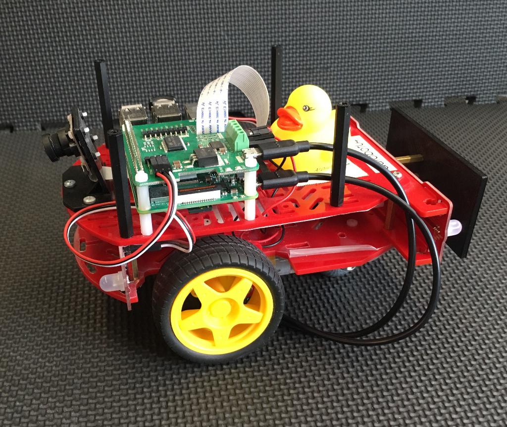
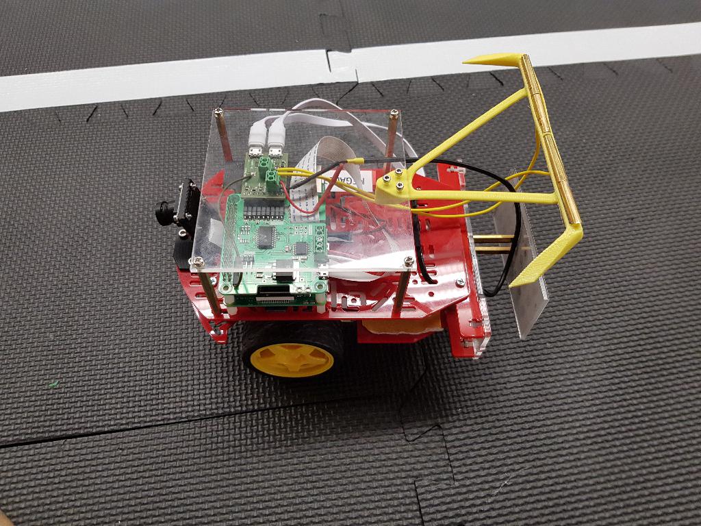
If you want to use the autocharging feature, you will have to swap the Raspberry Pi to the top part of the Duckiebot. This is due to additional hardware that will be added. So your Duckiebot should look like Figure 1.1. As the batteries do not fit underneath the chassis you will have to get creative about where to place the battery.
If you want to be super safe you might want to add a Pin protector to ensure the pins will not be shorted when the Raspberry Pi is mounted on top of your Duckiebot. You can 3D print the protector with the link provided above or if you do not have a 3D printer available, use one of the many websites that offer 3D printing services such as sculpteo.

For localization
✎Modified 2019-09-26 by hosnerm
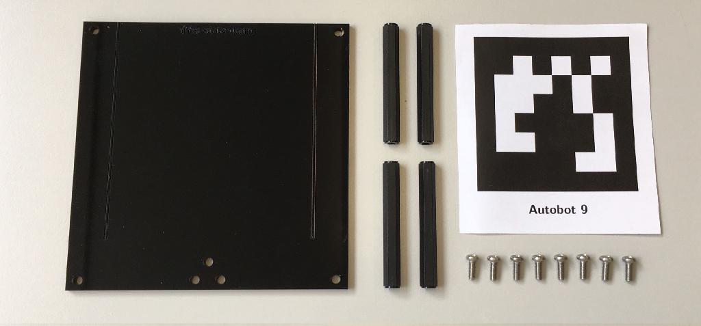
Material needed for the localization standoff
✎Modified 2019-11-21 by hosnerm
- 4 standoffs M3 x 50mm for example from here
- 8 screws M3 * 8mm
- laser cut top plate
- printed April tags
Assembly
✎Modified 2019-09-26 by hosnerm
Do not get confused by having the Raspberry Pi on top in the instructions. If you do not plan to use autocharging, there is no need to have it on top.
First of all, attach the screws and standoffs to the Duckiebot. It is important that you use the same mounting position as we do in Figure 1.4 because the localization system assumes the April tag to sit on a certain spot of the Autobot. If you place it differently, the localization will be imprecise.

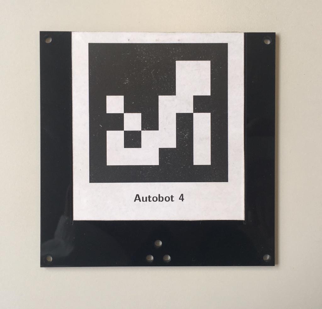
Attach the printed April tag on your top plate. TIP: print the April tags directly onto self-attaching paper so you don’t need to add any glue or similar and can easily remove the April tags if needed. Here it is also important that you attach the April tag the exact same way as we do in Figure 1.5 for the same reason as above. The April tag needs to be aligned with the engraving and the front edge and have the same orientation.
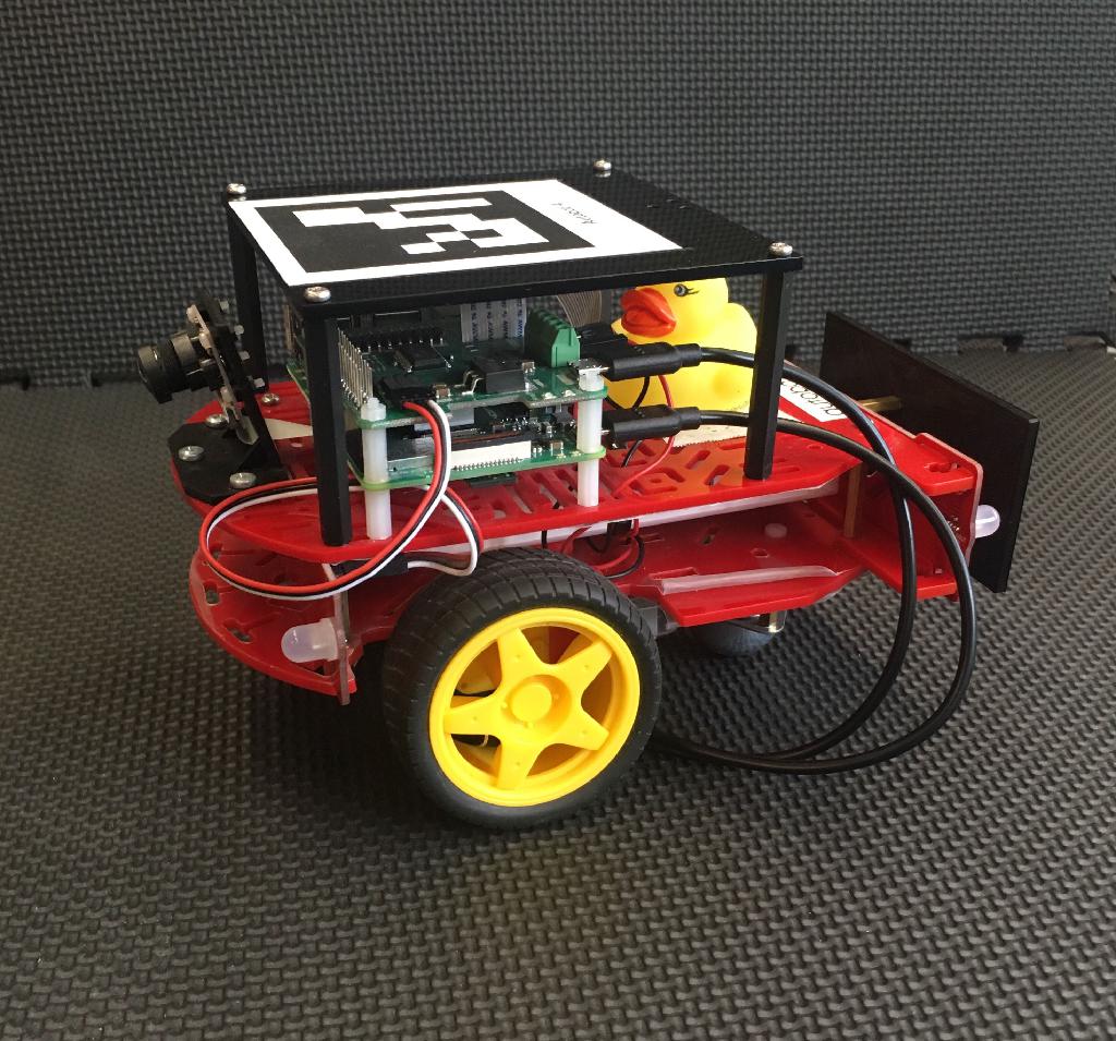
You can now attach the top plate to the Autobot. The result should look like Figure 1.6
For autocharging
✎Modified 2019-09-26 by hosnerm
In order to let a Duckiebot charge in a charger, additional hardware is needed. This piece is called the current collector.
Material for a single current collector Subsection 1.4.1 - Material needed for a single current collector
A Duckiebot capable of charging Figure 1.7.
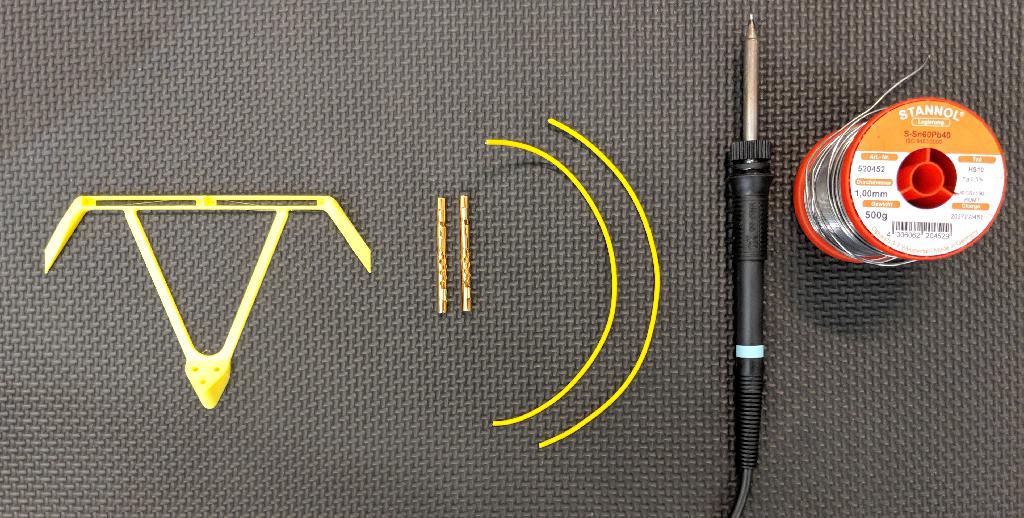
Material needed for a single current collector
✎Modified 2019-09-26 by hosnerm
- 6 laboratory plug CAT I Ø4mm
- 2 1mm cable, length 30cm
- Autolab add-on board (get in touch on slack to find out how to get them)
- If printer available: Material for the 3D printer (cutest color is yellow)
- April tag plate
- 16 plastic spacers M2.5 12mm or 4 spacers M2.5 50mm
- 7 screw M2.5 10mm and nut M2.5
- Open ended USB cable 20cm
- Soldering iron and solder
Assembly
✎Cut / Order the April tag plate
✎If a laser cutter is available, then laser cut this file with the dimensions (you probably need to scale it, depending on your programs units).
If no laser cutter is available, then order this file with the dimensions from a page, for example https://www.sculpteo.com/en/.
Print / Order the current collector
✎If a 3D printer is available, then just follow these instructions.
If no 3D printer is available, then order the printed part from this site.
Put together three laboratory plugs
✎Take three laboratory plugs and put them together as seen in Figure 1.8.

Prepare the current collector soldering
✎Be sure to have everything ready in Figure 1.9
Solder the wires
✎Solder the wires to the laboratory plugs as seen in Figure 1.10.

Put the cables through the 3D printed part as seen in Figure 1.11.

Optional: Glue the laboratory plugs
✎If for any reason the laboratory plugs do not fit tightly in the 3D printed part, glue them.
Prepare the assembly
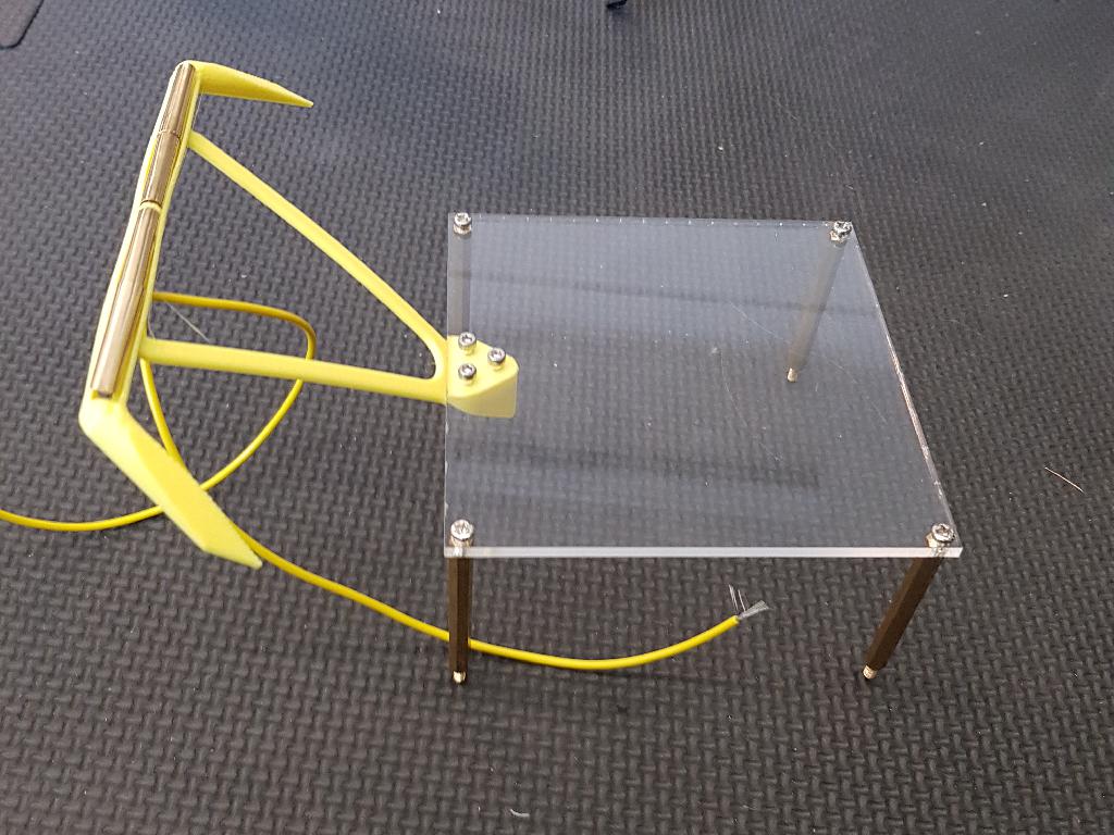
✎Make the parts ready as seen in Figure 1.12.

Assemble the April tag plate
✎Assemble the April tag plate by using the acrylic glass, screws and distance keepers as seen in Figure 1.13
Mount current collector to April tag plate
Mount the current collector by using three screws and nuts as seen in Figure 1.14

Plug in the Autolab add-on board
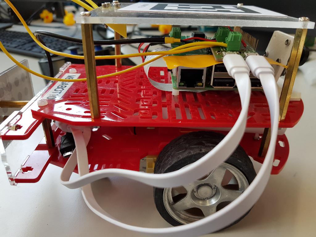
✎Plug in the Autolab add-on board as seen in Figure 1.15. Also, screw the cables from the current collector as well as the open ends from the open ended USB cable to the add-on board.

Mount the structure to the Duckiebot
✎Mount the April tag board with the current collector assembled to a Duckiebot as in Figure 1.17 and Figure 1.16. Plug in the USB cable to the battery of the Duckiebot.
Test your setup
✎Connect the brass pieces to a 5V voltage source and check if the battery signals that it is charging.