Part 1: Raspberry Pi and Power Distribution Instructions
✎Modified 2020-10-18 by sageshoyu
Expected Time: 3 hours
Preliminary Tasks
✎Modified 2020-07-21 by Garrett Warren
Charge the Battery
✎Modified 2020-08-05 by Garrett Warren
- Start charging your drone battery so it is ready when you need it.
Never leave the battery charging unattended. The battery takes about 2 hours to charge
Download Image and Image Flashing Software
✎Modified 2020-09-03 by Garrett Warren
-
If you have not already, on a base station, download the image flashing tool Etcher.
-
If you have not already, on a base station, download the latest drone image.
-
Connect the micro SD card to the workstation. Use the micro SD to USB card reader if the base station does not have a micro SD port.
-
Open Etcher and select the downloaded drone image. Then select the micro SD card as the drive to flash. Finally, click the “Flash” button.
Double check that the “drive” is your micro SD card. You may be prompted to enter the base station password to proceed. This is normal; flashing an SD card deletes everything that is on it, so Etcher is making sure this process is OK with you.
flashing will take 1 - 2 hours. In the meantime, you can move on to the next sections.
Attach the Pin Header to the Pi Hat
✎Modified 2020-07-21 by Garrett Warren
Identify the front and back
✎Modified 2020-08-05 by Garrett Warren
Identify the side of the Pi Hat that has writing on it - this side is the front, and the side without writing is the back. Tip: take note of where the slot slot in the Pi Hat to help with matching the orientation in the following instructions.


Insert the Pin Header
✎Modified 2020-08-05 by Garrett Warren
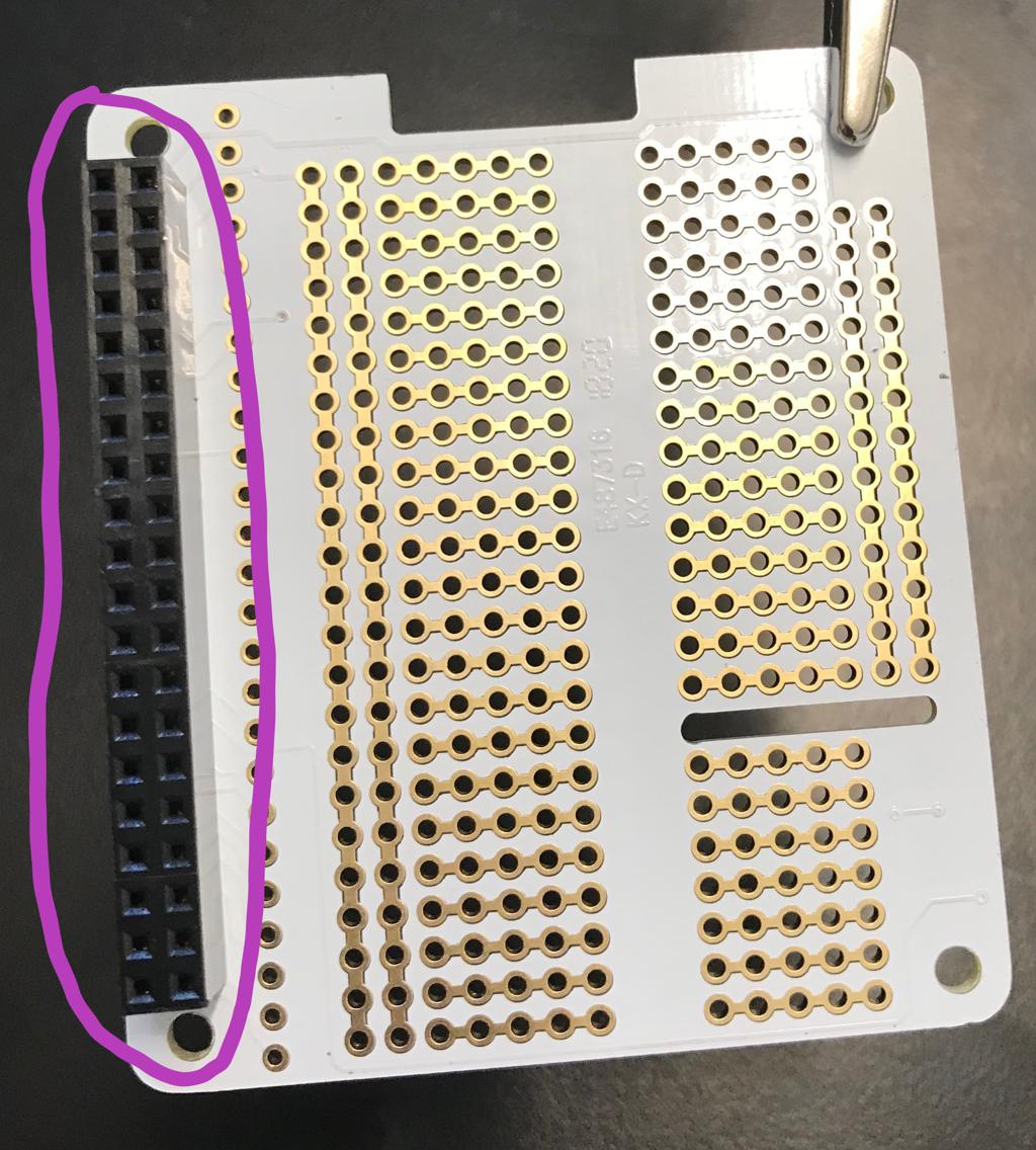
Insert the Pin Header into the back of the Pi Hat as shown in the image
Solder the Pin Header
✎Modified 2020-08-05 by Garrett Warren
-
Review the through-hole soldering technique
-
Use the helping hands to assist as you solder the pin header
video tutorial: video instructions part 1
video tutorial: video instructions part 2
video tutorial: video instructions part 3
It’s very easy to add too much solder and create a solder bridge between adjacent pins. Visually inspect your soldering to make sure that adjacent pins are not connected by globs of solder. If you have a solder bridge, try the technique shown in this video. If this does not work, you can use desoldering wick or a solder sucker to remove the excess solder.
Sometime too much heat when soldering the pin header can mess up the Pi Hat connections. To make sure the connections are still good, do a connectivity check on the Pi Hat; verify there is:
- A short between the hole labelled SDA on the Pi Hat and the pin at row 2 column 1 of the pin header that you soldered.
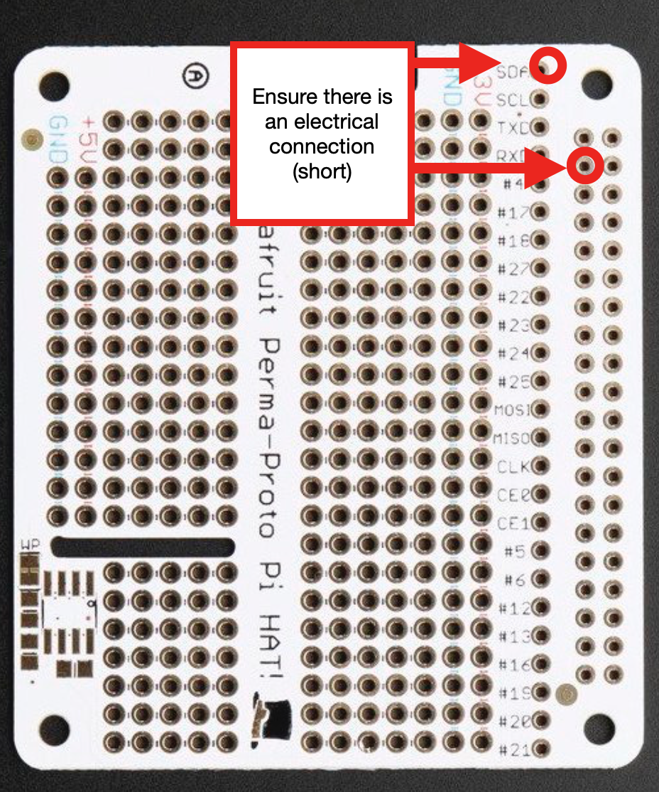
- A short between the hole labelled SCL on the Pi Hat and the pin at row 3 column 1 of the pin header that you soldered.

If you make a mistake while soldering, review the instructions for fixing soldering mistakes
Attach the LED and Resistor to the Pi Hat
✎Modified 2020-10-26 by GarrettWarren
Solder the 680 Ohm resistor and your LED to the Pi Hat as shown in the image.
The value of the resistor can be modified to adjust the brightness of the LED at full power. If you have additional resistors, you can modify this resistance by using a resistor with a smaller resistance, or by adding resistors in parallel later on. A helpful thread for understanding why this resistance should work is found here.
The direction of the resistor does not matter, but the direction of the LED does matter. Be sure to place the cathode (shorter end) into the GND rail.
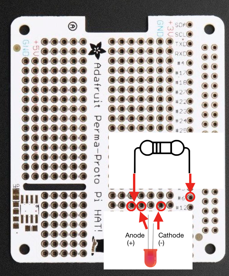
You’ve just finished the LED circuit! In a future lesson, you will learn how to send electricity through GPIO pin #6 to the LED and resistor, and then back to ground.
Attach the BEC to the Pi Hat
✎Modified 2020-07-21 by Garrett Warren
Prepare
✎Modified 2020-08-05 by Garrett Warren
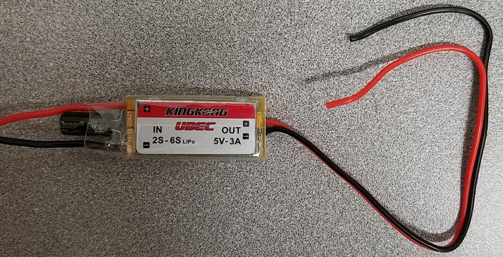
Cut the black plastic piece off the BEC OUT wires

Strip and Tin
✎Modified 2020-08-05 by Garrett Warren
-
Strip the end of the red and black OUT wires (the wires you just cut) so that there is about 5mm of exposed wire.
-
Twist together the ends of the wires and lightly tin them. The wires need to be thin enough to fit through the holes in the Pi Hat.
Solder
✎Modified 2020-08-05 by Garrett Warren
Solder the BEC red (+) OUT wire to the +5V Rail, and solder the BEC black (-) OUT wire to the GND rail, as shown in the image.
Any hole on the rails will work; however, for wire organization, it is better to use a hole on the 5V rail that is shown. If you mess up soldering, it is ok to leave the mistake and use a different hole.

video tutorial: video instructions (please ignore the extra wires and components that are already attached to the Pi Hat in the video)
Do a connectivity check on the Pi Hat. Verify there is:
- no short between the +5V rail and the GND rail on the Pi Hat
Prepare the PDB
✎Modified 2020-08-05 by Garrett Warren
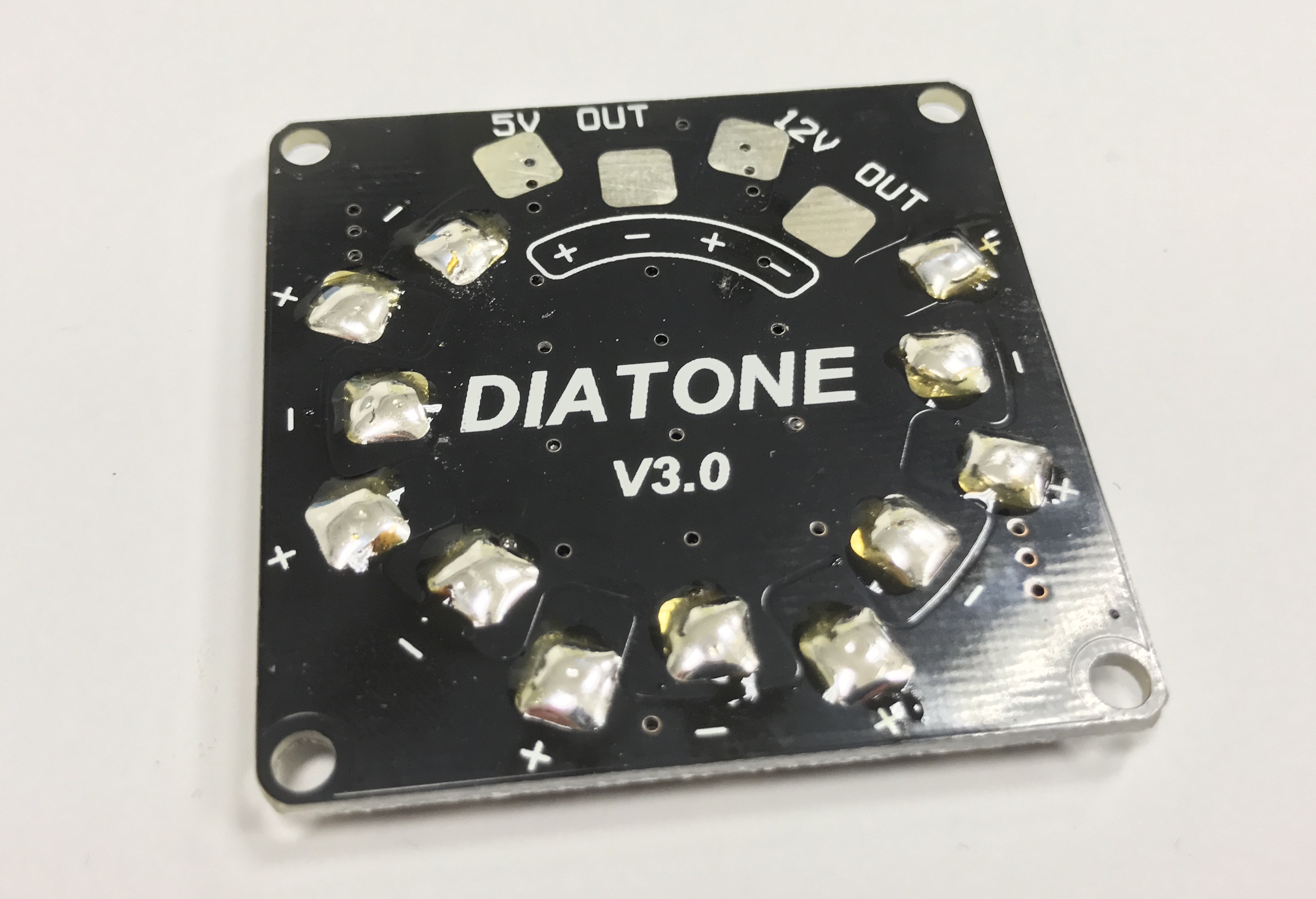
Tin the PDB
✎Modified 2020-08-06 by Garrett Warren
Similar to exposed wires, the metal pads on a PDB need to be tinned. This will allow tinned wires to be joined to the pads - and therefore the PDB.
-
Review the pad-tinning tutorial
-
Tin every pad on the PDB, except the 5V and 12V pads.
Be careful not to aggresively push the soldering iron tip into the PDB, as too much force will cut the pads right off!
video tutorial: video instructions
For the remainder of the instructions, unless stated otherwise, red wires should be soldered to positive (+) pads and black wires should be soldered to ground (-) pads.
Solder the BEC to the PDB
✎Modified 2020-07-21 by Garrett Warren
Tin
✎Modified 2020-08-05 by Garrett Warren
Tin the ends of the red and black wires that are connected to the side of the BEC that is labeled IN
Solder
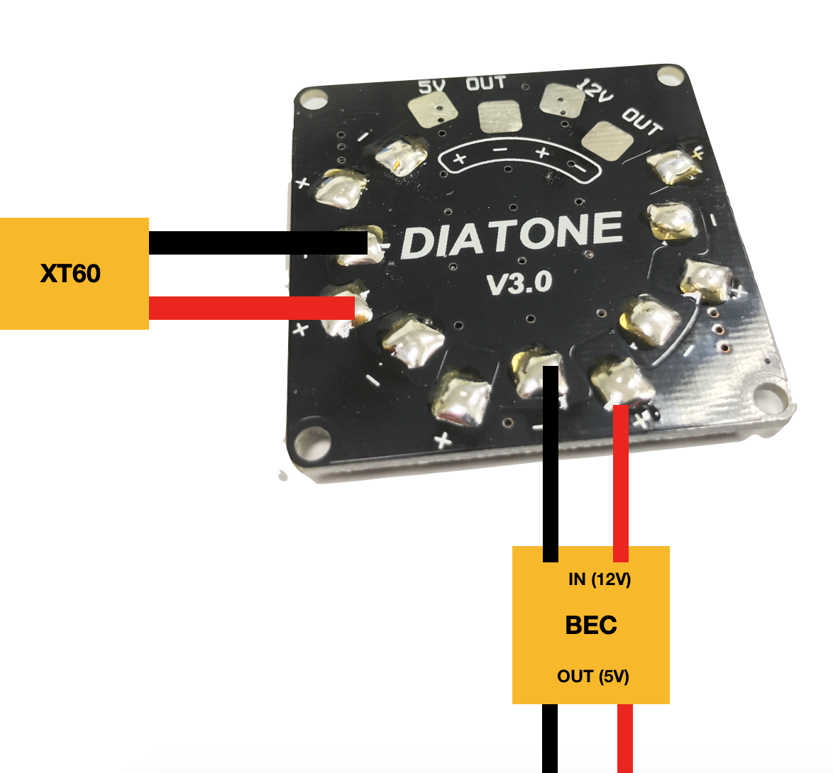
✎Solder the BEC red (+) IN wire to the positive (+) pad on the PDB, and solder the black (-) IN wire to the negative (-) pad on the PDB, as shown in the image.
Any of the tinned (+) pads will work; however, using the pad shown in the image will help with wire organization later on.

video tutorial: solder BEC to PDB (Please ignore the additional wires on the PDB, as well as which pads the BEC is soldered to - just observe the technique)
Solder the XT60 Battery Connector to the PDB
✎Modified 2020-07-21 by Garrett Warren
Strip and Tin
✎-
Strip the ends of the battery connector so that about 1cm of wire is exposed
-
Tin the exposed ends of the XT60 connector
Solder
✎Solder the XT60 red (+) wire to the tinned positive (+) pad on the PDB, and solder the black (-) wire to the tinned ground (-) pad on the PDB, as shown in the image.
This wire is very thick and it will take a while for the solder to melt. Make sure your soldering iron is turned all the way up and be patient.
Do not solder the wires flat against the PDB - solder them at ~20° angle away from the board. If you solder them flat, then you will not be able to fit the PDB into the drone frame.
Visually inspect the drone to verify the following:
-
All red wires connected to the PDB are connected to positive (+) pads
-
All black wires connected to the PDB are connected to negative (-) pads
-
The wires on the IN side - NOT the OUT side - of the BEC are soldered to the PDB
Do a connectivity check on the PDB; verify there is:
-
a short between any positive (+) pad and any other positive (+) pad
-
a short between any negative (-) pad and any other negative (-) pad
-
no short between any positive (+) pad and any negative (-) pad
ONLY if the connectivity check passed, do a DC voltage check on the PDB; plug in a 12V battery and verify there is:
-
~0V between any positive (+) pad and any other positive (+) pad
-
~0V between any negative (-) pad and any other negative (-) pad
-
~12V between any positive (+) pad and any negative (-) pad.
If the battery is X volts instead of 12 volts (e.g. 10), then the multimeter will show X volts instead of 12 volts.
ONLY if the DC voltage check passed, re-connect a battery to your drone and verify the following:
- The bottom of the drone frame is illuminating, due to the LEDs on the bottom of the PDB.
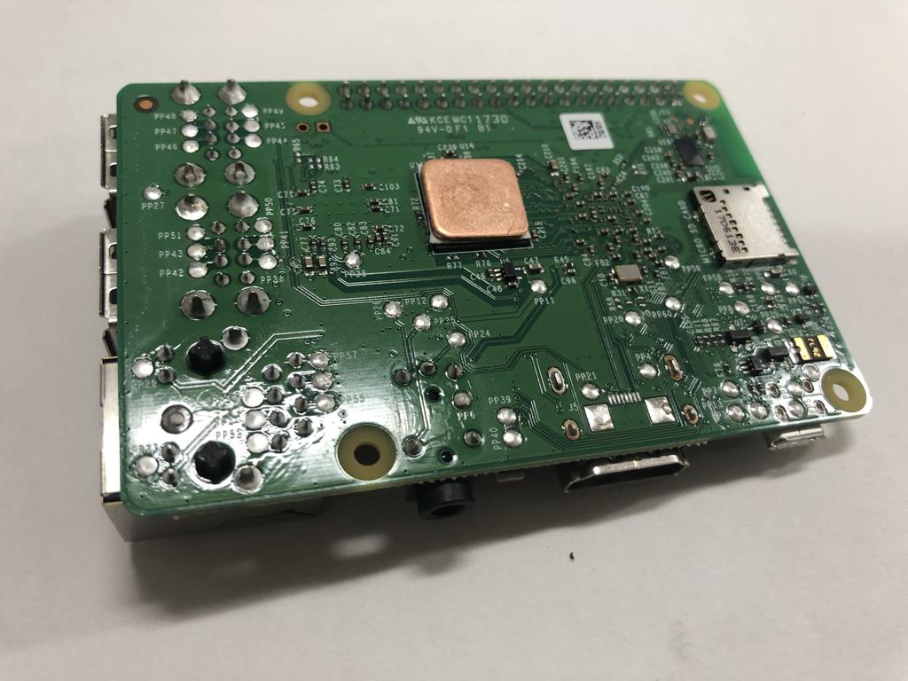
Put Heat Sinks on Raspberry Pi
✎Modified 2020-08-31 by Garrett Warren
Attach the heat sinks to the Pi as shown in the pictures.

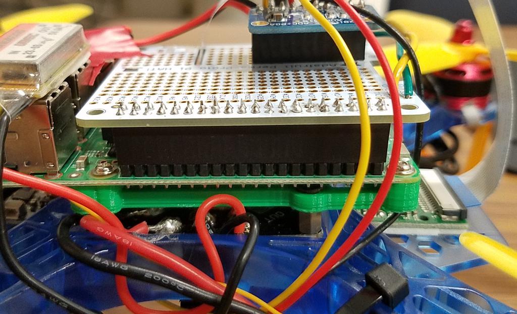
Attach the Pi Hat to the Pi
✎Modified 2020-08-06 by Garrett Warren
Align the pins
✎Modified 2020-08-05 by Garrett Warren
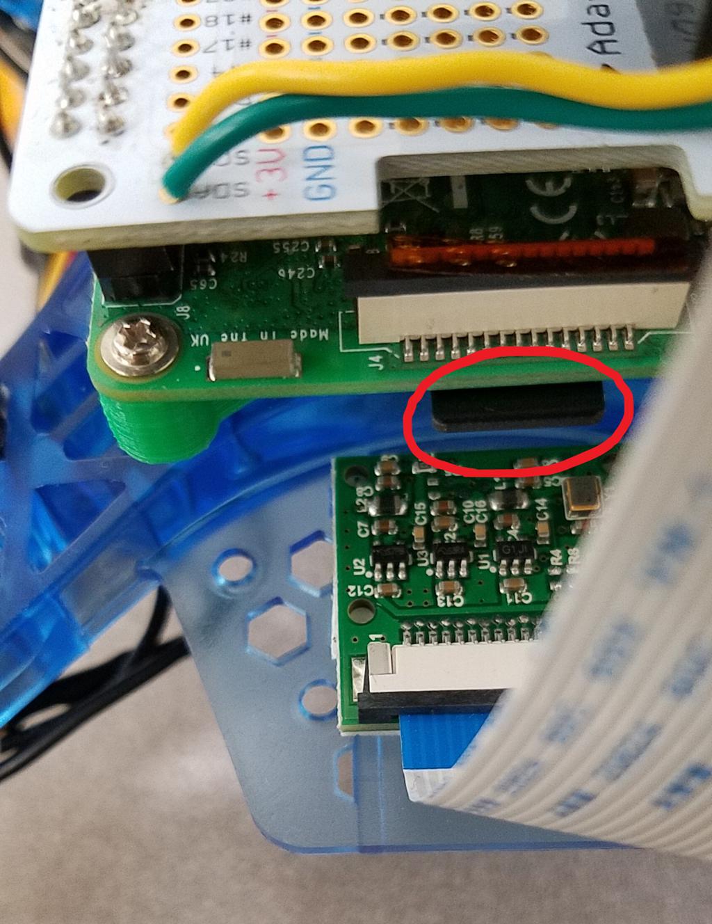
Align the 2x40 GPIO pins on the Raspberry Pi with the 2x40 pin header that you soldered to the Pi Hat as shown in the image. (please ignore additional wires on the Pi Hat)
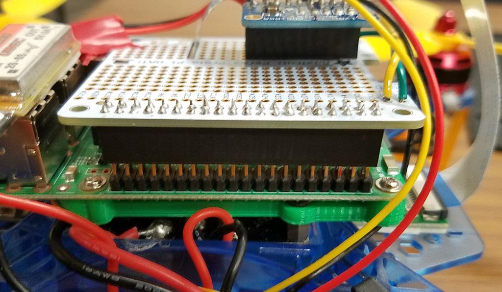
Press down
✎Modified 2020-08-05 by Garrett Warren
Press the pin header down onto the GPIO pins to connect the Pi Hat
Final Steps
✎Modified 2020-08-05 by Garrett Warren
Do another connectivity check to verify that there is no short between the +5V rail and the GND rail on the Pi Hat.
Verify that the Pi has power
✎Modified 2020-08-05 by Garrett Warren
-
Connect the battery
-
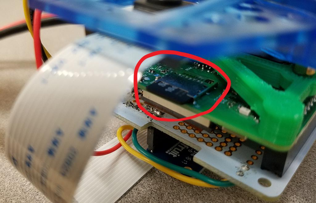
Verify that the BEC has a solid greed light.
-
Verify that the Pi has a solid red light.
Insert the SD card into the Pi
✎Modified 2020-08-05 by Garrett Warren
Insert your (now flashed) SD card into the SD card slot on the bottom of the Pi.
The SD card direction does matter - the lettering on the SD card should be facing downward.