Part 3: Motors, and ESCs Instructions
✎Modified 2020-10-18 by sageshoyu
Expected Time: 5 hours
Sometimes parts will have wires already tinned out-of-the-box by the manufacturer (i.e. pre-tinned). You can identify this by: 1) the “shininess” of the tip of a wire and 2) the inability to fray the wire strands of the tip of a wire. However, such tinning is often ineffective. Cut off any pre-tinned tips, then strip and tin the part yourself.
Solder wires onto ESC pads
✎Modified 2020-07-21 by Garrett Warren
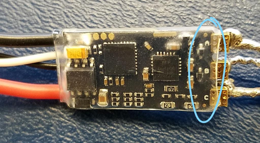
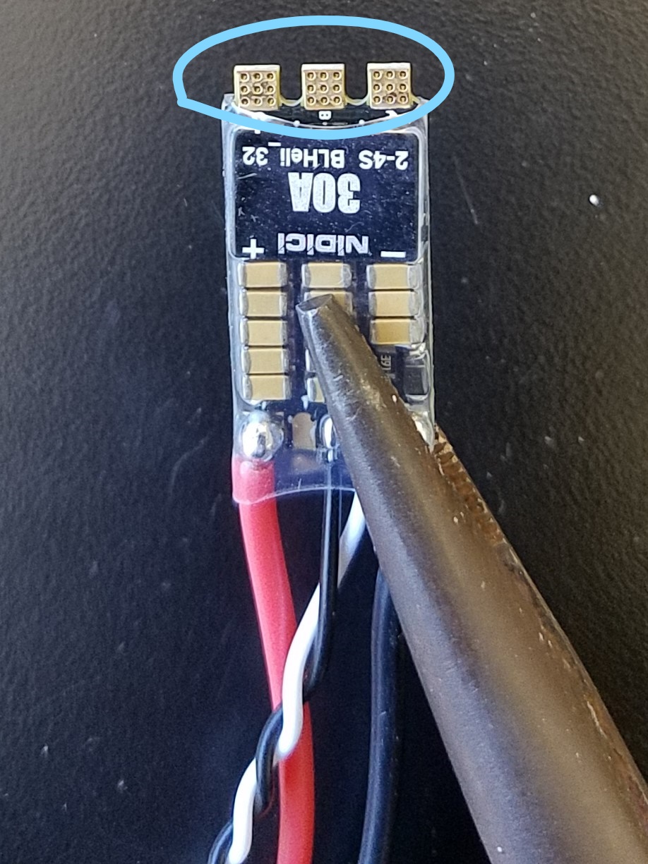
In this section, you will prepare your ESCs. Each ESC has 3 pads labeled A, B, and C. The labels are on the bottom of the ESC:
Cut ESC wires to length
✎Modified 2020-08-05 by Garrett Warren
-
Cut four pieces of the blue wire, 3 inch lengths
-
Cut four pieces of the yellow wire, 3 inch lengths
-
Cut four pieces of the red wire, 3 inch lengths
Tin the ESC wires
✎Modified 2020-08-05 by Garrett Warren
-
Strip about 5mm from both ends of the each wire that you just cut (12 wires in total)
-
Tin both ends of the wires
Prepare the ESC:
✎Modified 2020-08-05 by Garrett Warren
Use your fingers (or small wire cutters) to very carefully remove excess material from each ESC pad.

Tin the ESC pads
✎Modified 2020-08-05 by Garrett Warren
Tin all three metal pads on each of the four ESCs
Solder the ESC wires to the ESCs
✎Modified 2020-08-06 by Garrett Warren
-
Review the wire-to-pad soldering technique
-
Use the helping hands to hold one ESC in place for solder
-
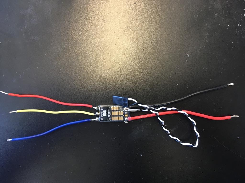
Solder the yellow wire to the middle pad (pad “B”)
-
Solder the red wire to pad “A”
-
Solder the blue wire to pad “B”
-
Lightly pull the wire soldered to the pad and verify it stays on.
-
Do a connectivity check between each pair of soldered wires (recommend doing this now instead of in checkoff later). The multimeter should not beep, otherwise there is a short between the pair; if the multimeter does hold a continuous beep, then you will need to fix the short by removing any excess solder forming a bridge between the problematic pair of wires.


Insulate the ESC wires
✎Modified 2020-08-06 by Garrett Warren
Put a heat shrink over the ESC. The heat shrink should cover (length-wise) the exposed soldered wires on one end and half the ESC on the other end. Apply heat to shrink the heat shrink.

Repeat the above steps for each ESC
ESC bullet connectors
✎Modified 2020-08-05 by Garrett Warren
In this step you will solder bullet connectors onto the ESC wires and the motor wires so that you can easily connect them later on.
Review soldering tutorial
✎Modified 2020-08-06 by Garrett Warren
Before beginning this section, please refer to a bullet connector soldering tutorial.
You can use any setup to hold the bullet connector, so long as the setup is not thermally conductive. Also, if you have trouble soldering the bullet connectors, you may need to use a smaller soldering iron tip. Wait at least 15 minutes or longer for the soldering iron to completely cool down after unplugging before attempting to swap the soldering iron tip.
Strip and Tin the ESC power wires
✎Modified 2020-08-05 by Garrett Warren
-
Strip about 5mm from the ends of the red and black wires on each ESC
-
Tin the red and black wires on each ESC
Solder the socket bullet connectors to the ECS wires
✎Modified 2020-08-05 by Garrett Warren
For each ESC:
-
Solder a socket bullet connector to the end of each of the 3 ESC wires (i.e. red, yellow, blue).
-
Put a heat shrink over each solder joint. For socket connectors: the heat shrink should cover the solder joint on one end and run the entire length of the bullet connector. Apply heat to shrink the heat shrink.

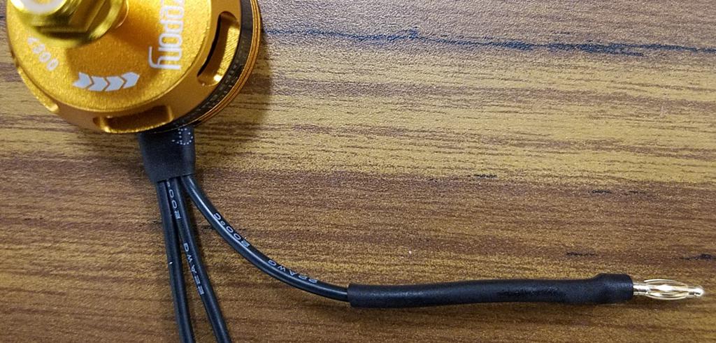
Motor bullet connectors
✎Modified 2020-08-05 by Garrett Warren
Strip the motor wires
✎Modified 2020-08-05 by Garrett Warren
- Strip about 5mm from the ends of the three black wires on each motor
Tin the motor wires
✎Modified 2020-08-05 by Garrett Warren
- Tin the ends of the three black wires on each motor
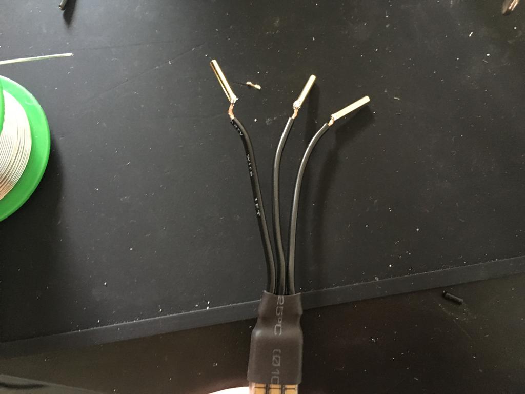
Solder the plug bullet connectors to the motor wires
✎Modified 2020-08-06 by Garrett Warren
For each motor:
-
Solder a plug bullet connector to each of the motor’s wires.
-
Put a heat shrink over each solder joint. For male connectors: the heat shrink should cover the solder joint on one end and run only the short length of the cylindrical part. Apply heat to shrink the heat shrink.

Visually inspect each ESC and verify that the heat shrinks are on properly; there should be no exposed wires and each heat shrink should be a tight fit.
-
Visually inspect that each of the following is stripped and tinned: 4 ESCs, 4 motors
-
Do a connectivity check on the XT60 connector cable; verify there is no short between the red and black wire.
-
Do a connectivity check on each ESC; for each ESC, verify there are no shorts between any two wires you soldered.
Solder ESCs to the PDB
✎Modified 2020-07-21 by Garrett Warren
An ESC (i.e. Electronic Speed Control) is a component which requires power. It takes this power and provides a variable amount of it to a motor; since a motor’s RPM depends on how much power it gets, an ESC can control how fast a motor spins by controlling how much power it supplies the motor.
Solder each of your 4 ESCs to the PDB.
✎Modified 2020-08-06 by Garrett Warren

Do not solder the wires flat against the PDB - solder them at ~20° angle. If you solder them flat, then you will not be able to fit the PDB into the drone frame.
Solder battery monitor leads to the PDB
✎Modified 2020-07-22 by Garrett Warren
Solder leads to PDB
✎Modified 2020-08-06 by Garrett Warren
Solder the 6 inch red and black wires to the PDB. Due to limited PDB pads, you will need to solder onto another pair of wires, e.g. BEC wires. The red wire should connect to a positive (+) pad and the brown wire should connect to a negative (-) pad.
these wires are soldered so they go across the PDB, toward where the flight controller will be mounted. Also, please ignore that in this photo, the PDB is in the drone frame.

While trying to solder on these wires, you may accidentally unsolder the existing wires from the PDB. We recommend temporarily holding down the existing wires with long-nose pliers, tape, or helping hands.
Solder to the flight controller
✎Modified 2020-08-06 by Garrett Warren
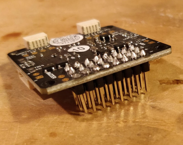
Solder the pins to the flight controller
✎Modified 2020-08-06 by Garrett Warren
Solder the short edge of the straight pins to the flight controller.
Be sure that direction you solder the pins into the board is exactly as shown in the images

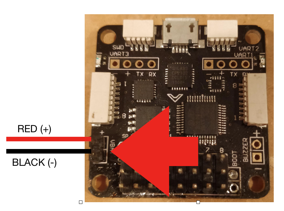
Solder the battery monitor leads to the flight controller
✎Modified 2020-08-06 by Garrett Warren
Tin and solder the battery leads to the flight controller as shown in the image
Attach parts to drone frame
✎Modified 2020-07-22 by Garrett Warren
This section will cover attaching the first set of items to the drone frame.
Before beginning, verify the PDB is completely soldered with all necessary parts (as covered in previous sections).
the flight controller is not shown in these images; however, don’t be alarmed that your build is incorrect. For now, just move the flight controller as you are working so it is not in the way. In the next section, you will attach the flight controller to the drone frame.
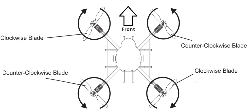
For reference, here are the motor directions with respect to the frame:
Materials
✎Modified 2020-08-06 by Garrett Warren
Gather the following:
- Drone frame
- Completed PDB
- 4 motors (2 CW, 2 CCW)
- Velcro
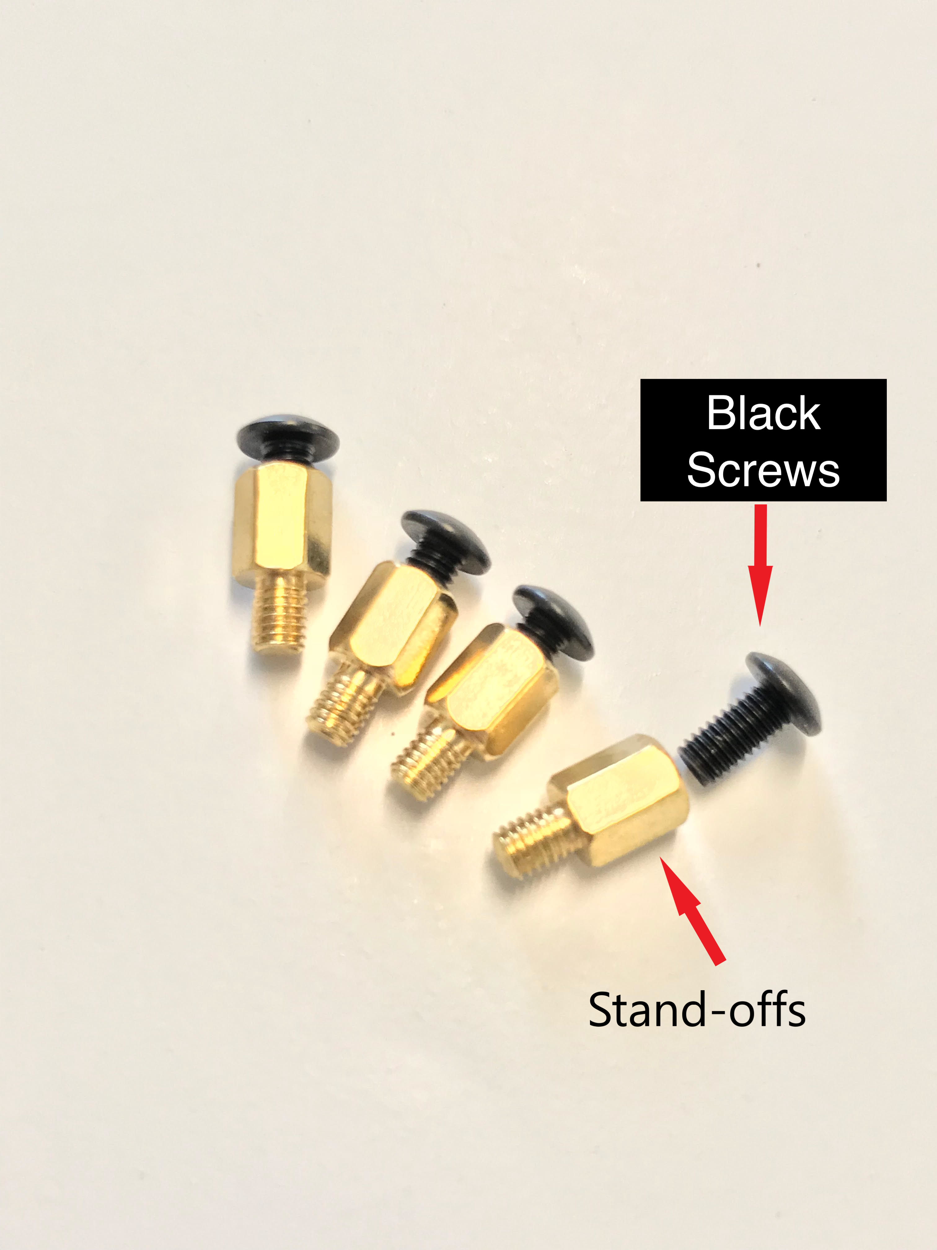
- 4 standoffs
- 12 black screws (in motors box, not drone frame box)
Align the frame
✎Modified 2020-08-06 by Garrett Warren
Place the drone frame on a flat surface so that the back is facing you.

Insert the velcro strap
✎Modified 2020-08-06 by Garrett Warren
Feed the velcro through the center of the drone frame. Make sure rough side is facing up.
The strap in the image is from a previous hardware version. You will want this to strap down around the battery on the bottom of the drone frame. Try doing so without the battery to make sure the strap is on in the correct direction.

Screw a short M3 motor bolt into each of the standoffs
✎Modified 2020-08-06 by Garrett Warren
Although the image shows rounded top bolts, the correct ones are the short M3 bolts that are included with the motors. (The ones shown in the image came from the frame kit and they work fine, but the hex key doesn’t fit them)
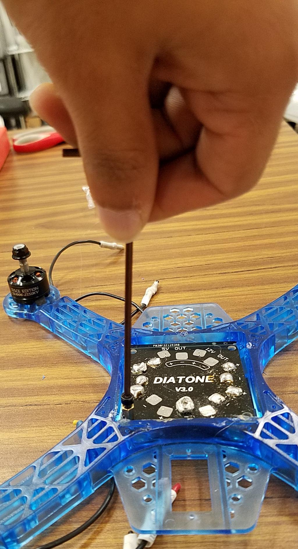
Attach PDB to frame
✎Modified 2020-08-06 by Garrett Warren
Place the completed PDB into the center of the drone frame. For each of the 4 corner screw holes of the PDB, screw a standoff through the hole and into the drone frame. Note that the drone frame doesn’t have screw grooves for the standoffs - you will create these grooves by applying downward force while screwing. Don’t screw too far, since it is easy to strip the plastic. (We realize these don’t hold into the frame that well, and are devising a better solution for the next hardware version.)

Attach clockwise (CW) motors
✎Modified 2020-08-06 by Garrett Warren
Attach CW motors to the bottom-right and top-left of the drone frame, using 2 black screws for each attachment.

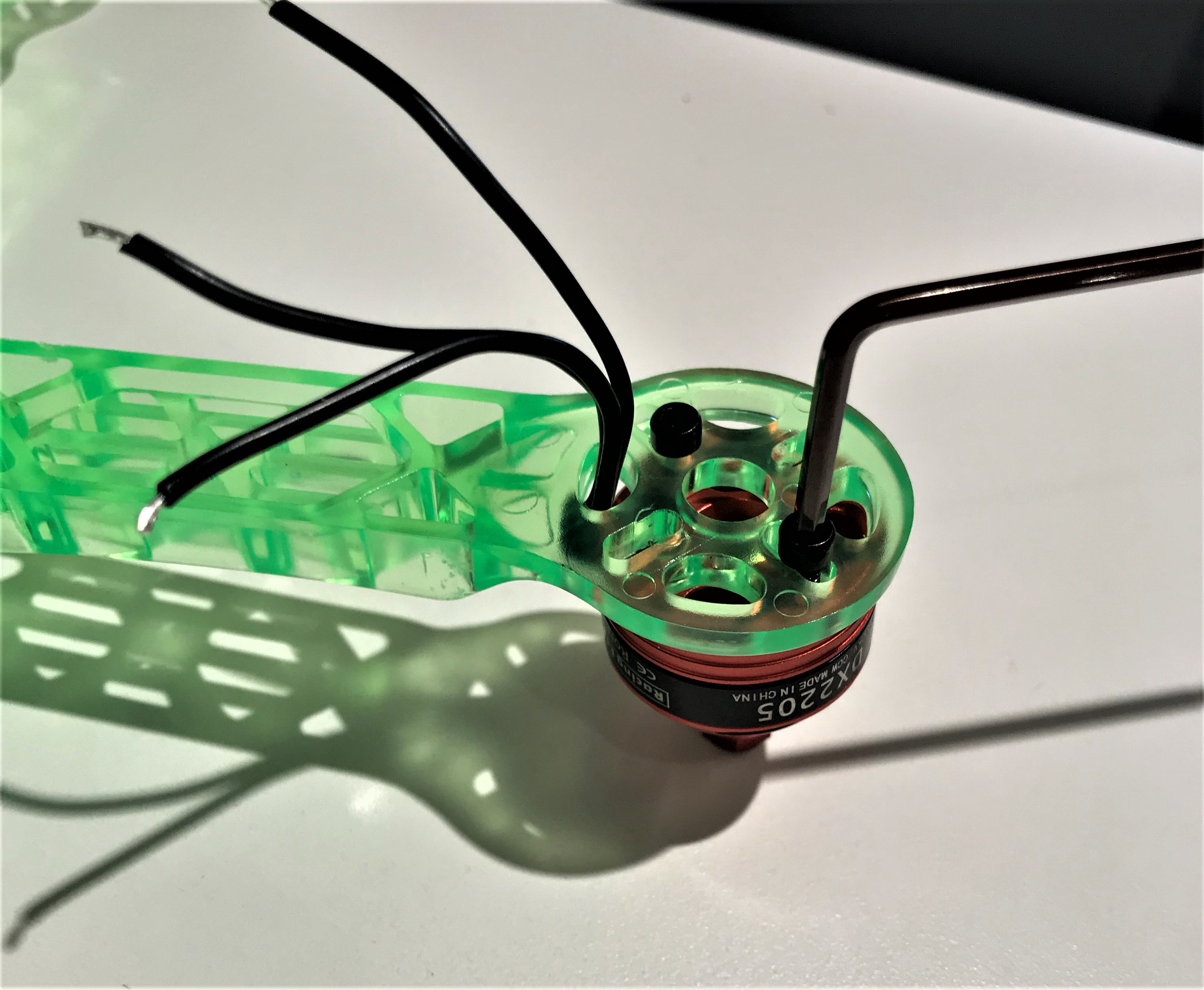
Attach Counter-Clockwise (CCW) Motors
✎Modified 2020-08-06 by Garrett Warren
Attach CCW motors to the bottom-left and top-right of the drone frame, using 2 black screws for each attachment.

Connect the Motors to the ESCs
✎Modified 2020-08-06 by Garrett Warren
For each motor, connect its plug bullet connectors to the socket bullet connectors of the ESC in the motor’s corner (e.g. top-left motor connects to top-left ESC). Any connection order will suffice for now, as you will be able to change them in a latter phase.
