Part 3: Flight Controller and Cleanflight Instructions
✎Modified 2020-10-18 by sageshoyu
Expected Time: 1 hour
Attach the Flight Controller
✎Modified 2020-08-06 by Garrett Warren
Trim
✎Modified 2020-08-06 by Garrett Warren
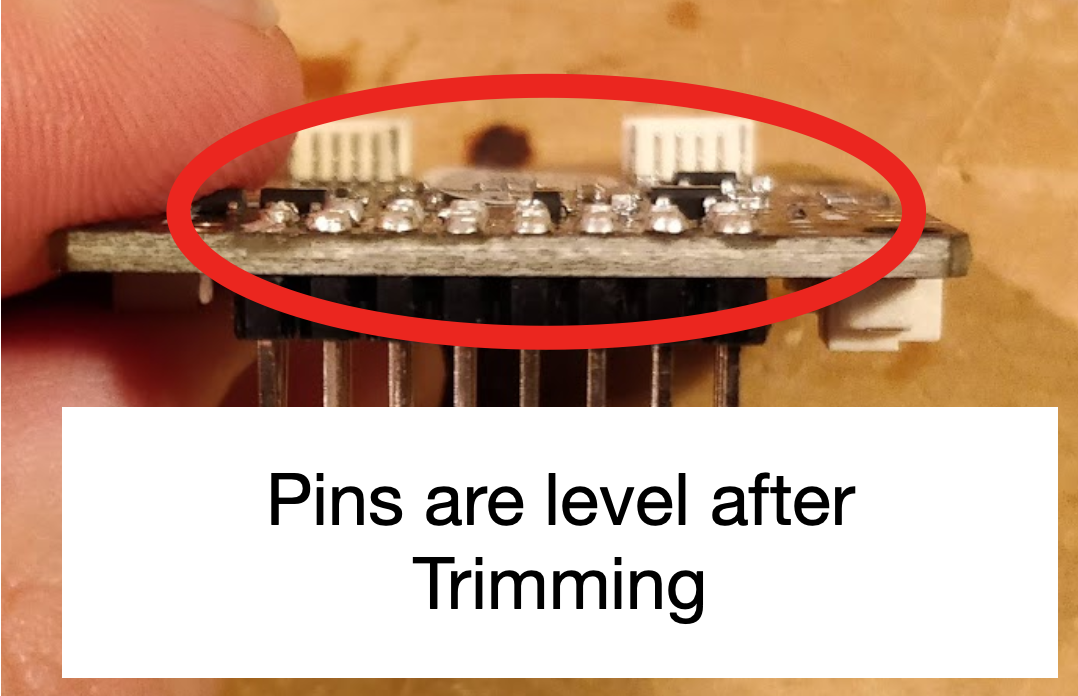
Trim the all of the pins on the flight controller just like the four shown in the image. This helps the flight controller sit level on the drone frame.
the image shows only 4 trimmed, but you will want to trim all of the pins (updated picture coming soon).

Apply Tape to the Bottom of the FC
✎Modified 2020-08-06 by Garrett Warren
-
Put double sided mounting tape on the bottom of the FC.
-
Cut off any excess tape.
Stick the FC to the drone frame
✎Modified 2020-08-06 by Garrett Warren
-
Peel off the back of the foam tape
-
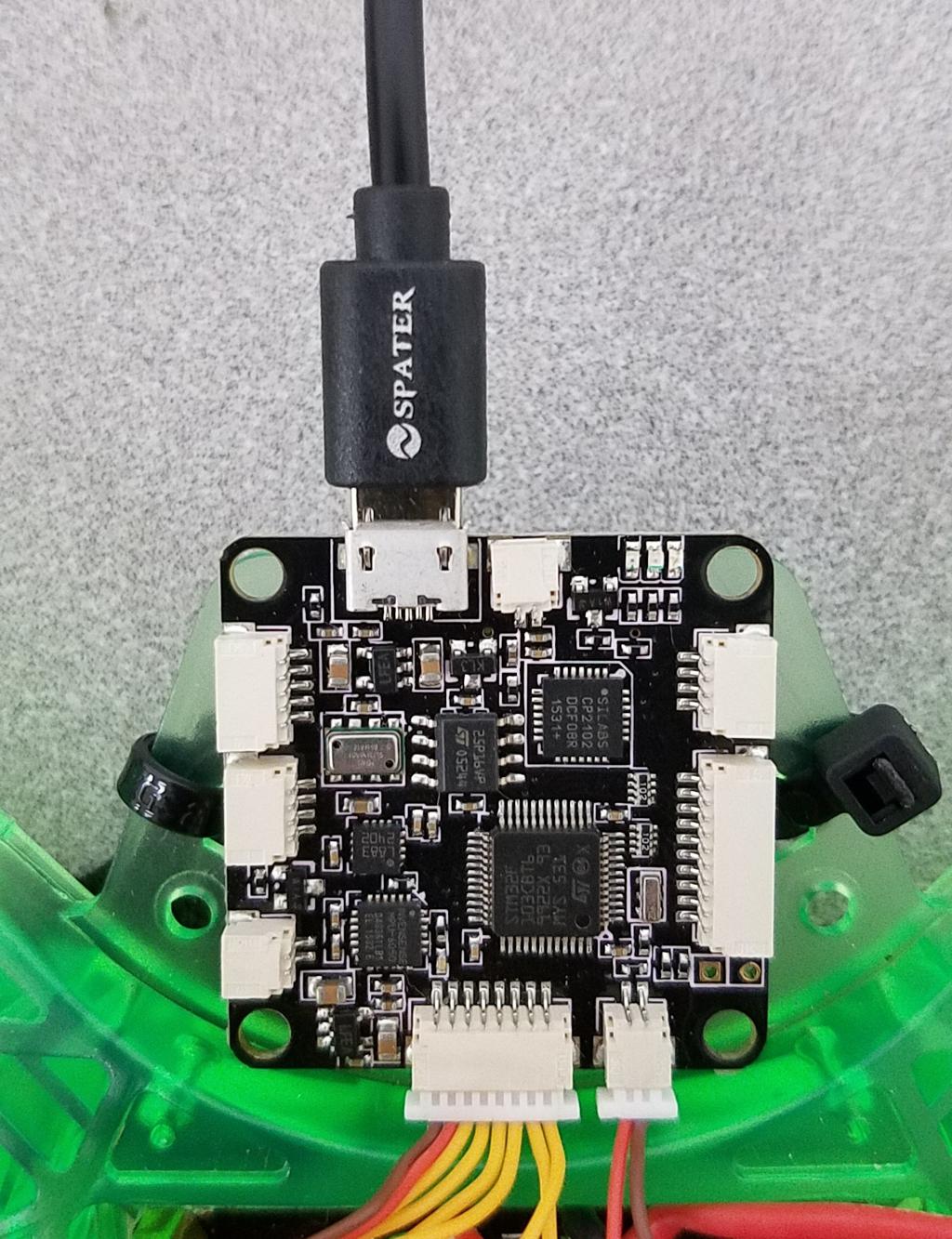
Attach the FC to front of the drone. Ensure the FC is not skewed and it is pushed against the frame body. (Ignore the extra wires in the flight controller for now).

the white plastic tabs will need to hang off the frame for the flight controller to sit level.

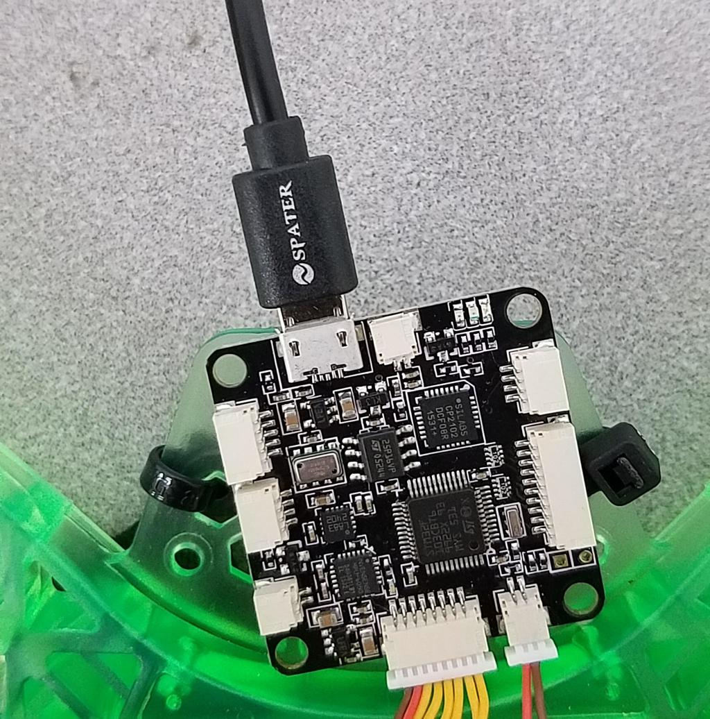
Try to minimize the FC skew as much as possible. (the following photos are an example of skew. ignore the difference of flight controller).
Once the FC is attached, do a “rock test” (i.e. try to rock the FC back-and-forth by pushing the corners). If the FC rocks, then the double sided mounting tape used is too soft and is compressing under pressure. Detach the FC from the frame (e.g. carefully use a flat-head screwdriver) and replace the tape with more robust tape.
Download the required software and files
✎Modified 2020-08-06 by Garrett Warren
Download the firmware
✎Modified 2020-08-06 by Garrett Warren
On your base station, download the flight controller firmware
the file extension for this file should be .hex. Your computer might have added a .txt to the end of the file, rename the file and delete .txt so that the file ends in .hex.
Install the USB to UART driver
✎Modified 2020-08-06 by Garrett Warren
A driver is software that allows your computer to talk to a hardware device. You will need a driver that allows the computer to talk to the flight controller.
-
On your base station, download this driver . Be sure to select the correct download for your base station’s operating system. If you are using a Chromebook, you will not need this driver.
-
Once downloaded, click on the file and go through the installation process
-
After the installation finishes, restart your base station.
Install Cleanflight
✎Modified 2020-08-06 by Garrett Warren
Cleanflight is open-source flight controller software that allows you to flash firmware to the flight controller, and configure the settings.
On your base station, install Cleanflight (you will need Google Chrome)
Flash the firmware
✎Modified 2021-04-12 by GarrettWarren
Please follow the written instructions below to flash firmware onto your flight controller. If you are having trouble flashing, please follow this video to flash the flight controller with the boot pins shorted.
Open the firmware flasher
✎Modified 2020-08-06 by Garrett Warren
-
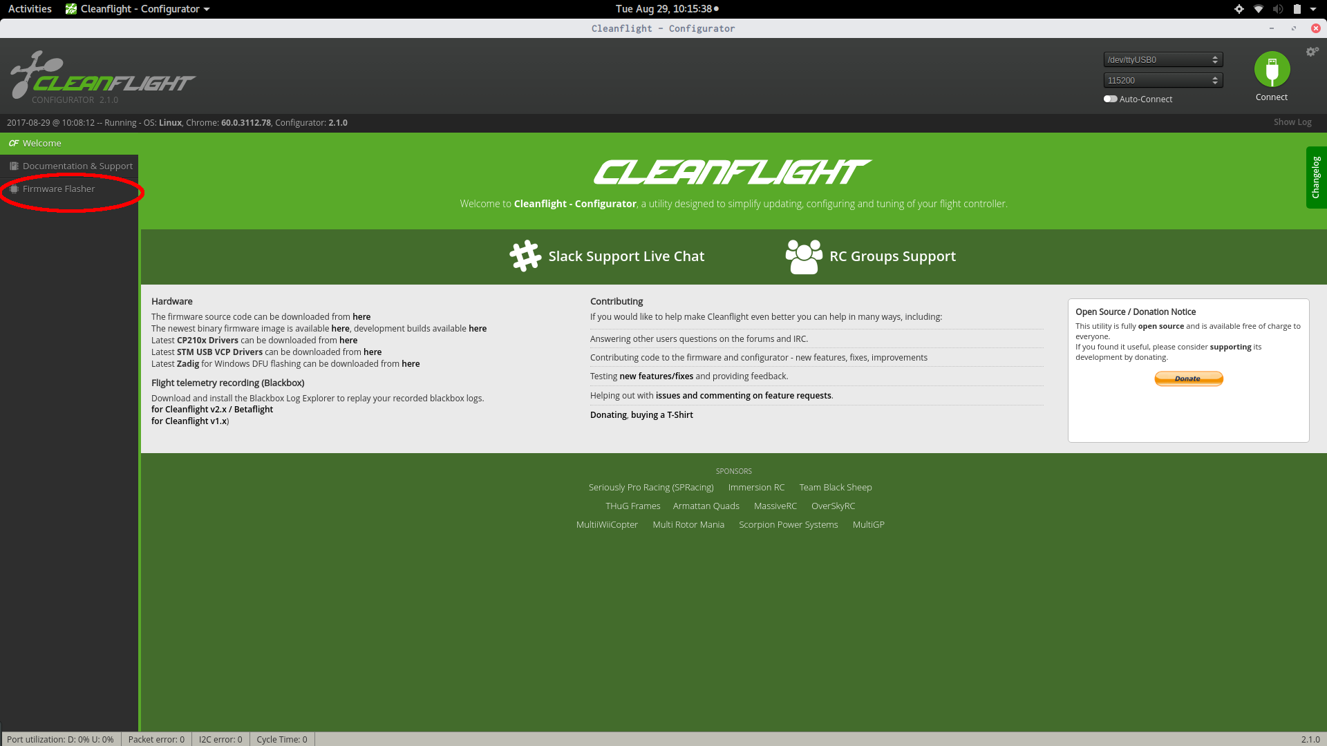
Launch CleanFlight
-
Click on “Firmware Flasher” on the left sidebar.
Load the firmware
✎Modified 2020-08-06 by Garrett Warren
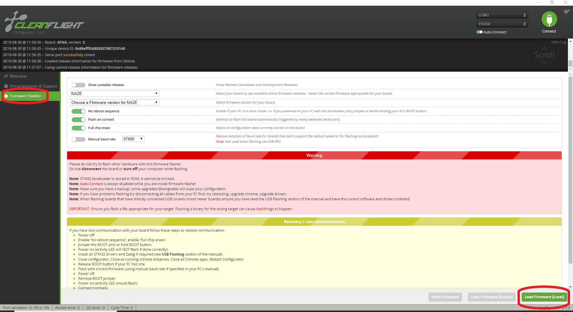
Click on “Load Firmware [Local]” in the bottom right corner of the window and select the firmware file that you downloaded (the one with the .hex extension).
Connect the FC
✎Modified 2020-08-06 by Garrett Warren
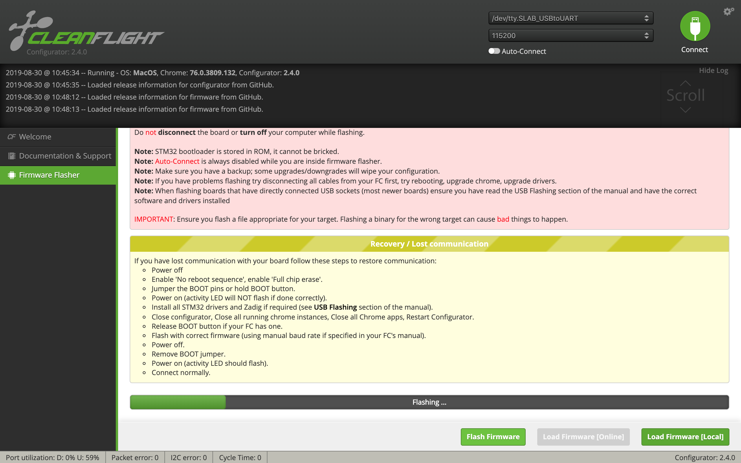
With the battery disconnected, connect the FC to the base station via a USB to micro USB cable. Click the flash firmware button at the bottom right of the screen. Flashing will be complete once the bar at the bottom of the screen says “Programming: SUCCESSFUL”.
If the bar instead reaches halfway and then says “Verifying: FAILED”, do not worry - it has flashed successfully.
Configure the Cleanflight settings
✎Modified 2020-09-01 by Garrett Warren
Now that the FC has been flashed with firmware, it can be configured.
Disconnect and Reconnect
✎Modified 2020-09-01 by Garrett Warren
-
Disconnect the FC from the base station and close Cleanflight.
-
Launch Cleanflight
-
Reconnect the FC to the workstation
-
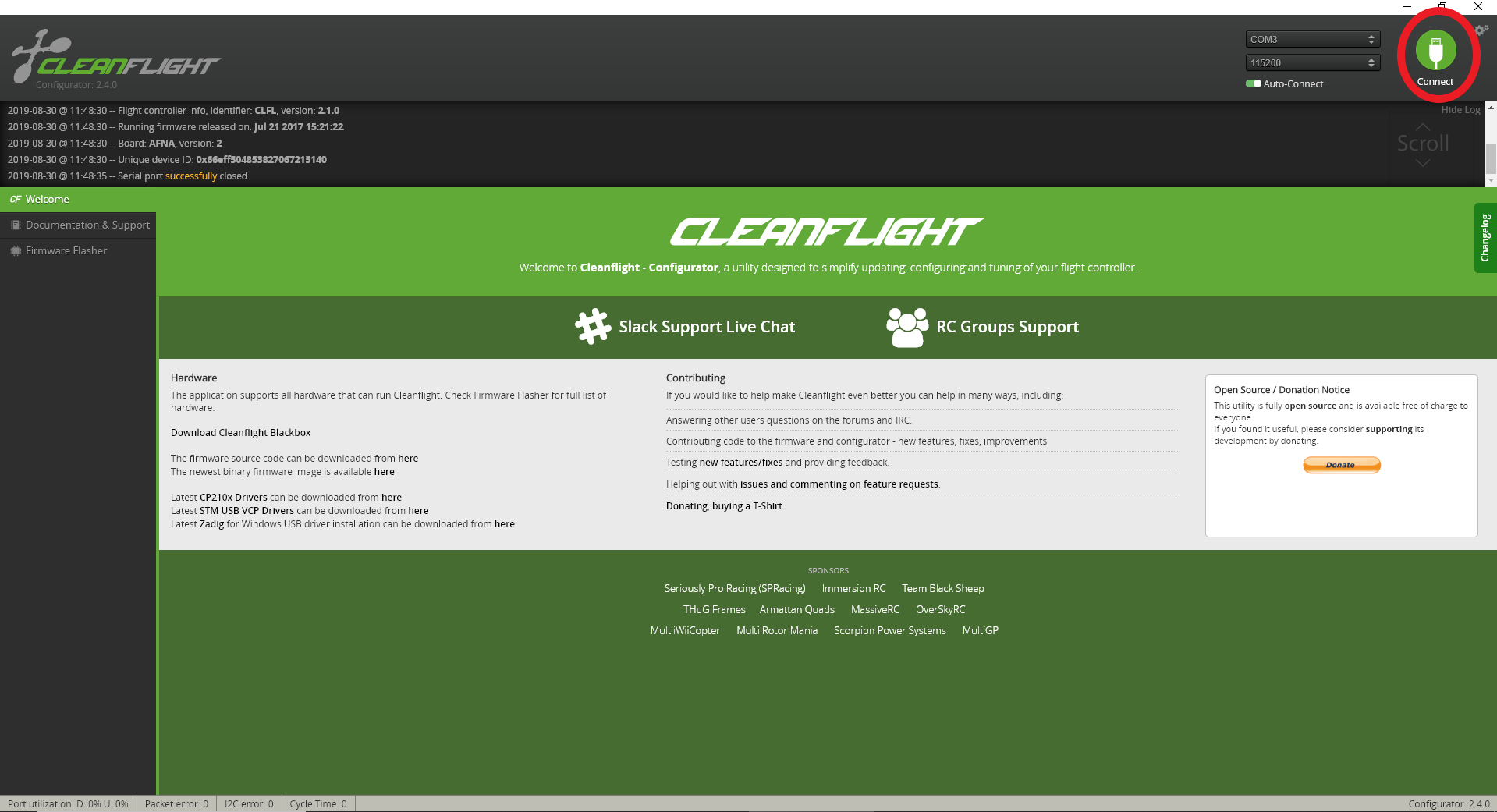
Click the “Connect” button in the top right corner of the screen (this is not needed if “auto-connect” is toggled on).
Now you will configure each of the settings that need to be changed.
“Ports”
✎Modified 2020-09-01 by Garrett Warren
-
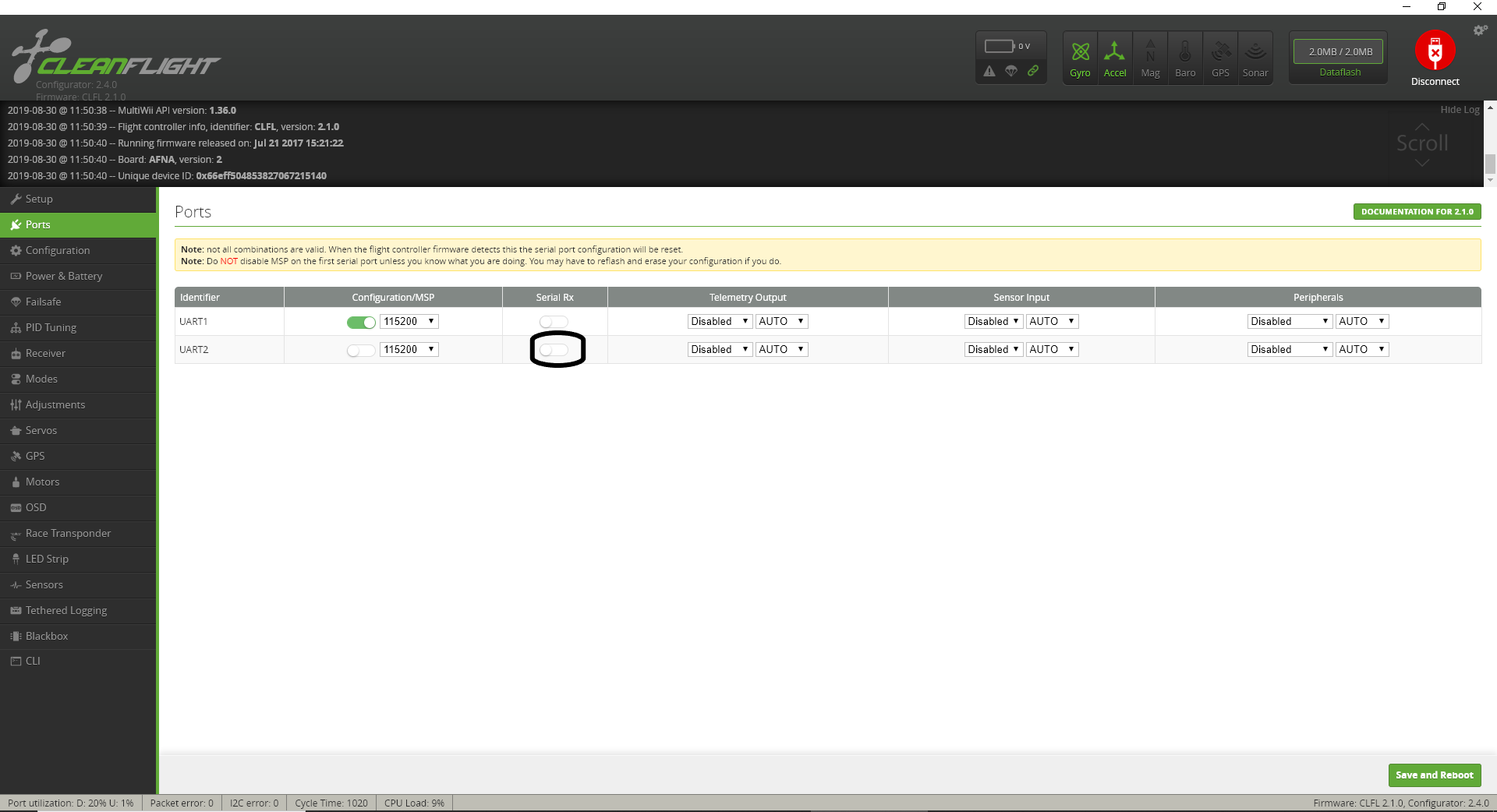
Go to “Ports” tab on the left side of cleanflight
-
make sure SerialRX for UART2 is disabled and click “Save and Reboot.” UART2 is a pin on the flight controller, and we want to make sure it only uses the USB.
“Configuration”
✎Modified 2020-09-01 by Garrett Warren
Go to “Configuration” tab on the left side of cleanflight
- Change the ESC/Motor protocol to “MULTISHOT”.
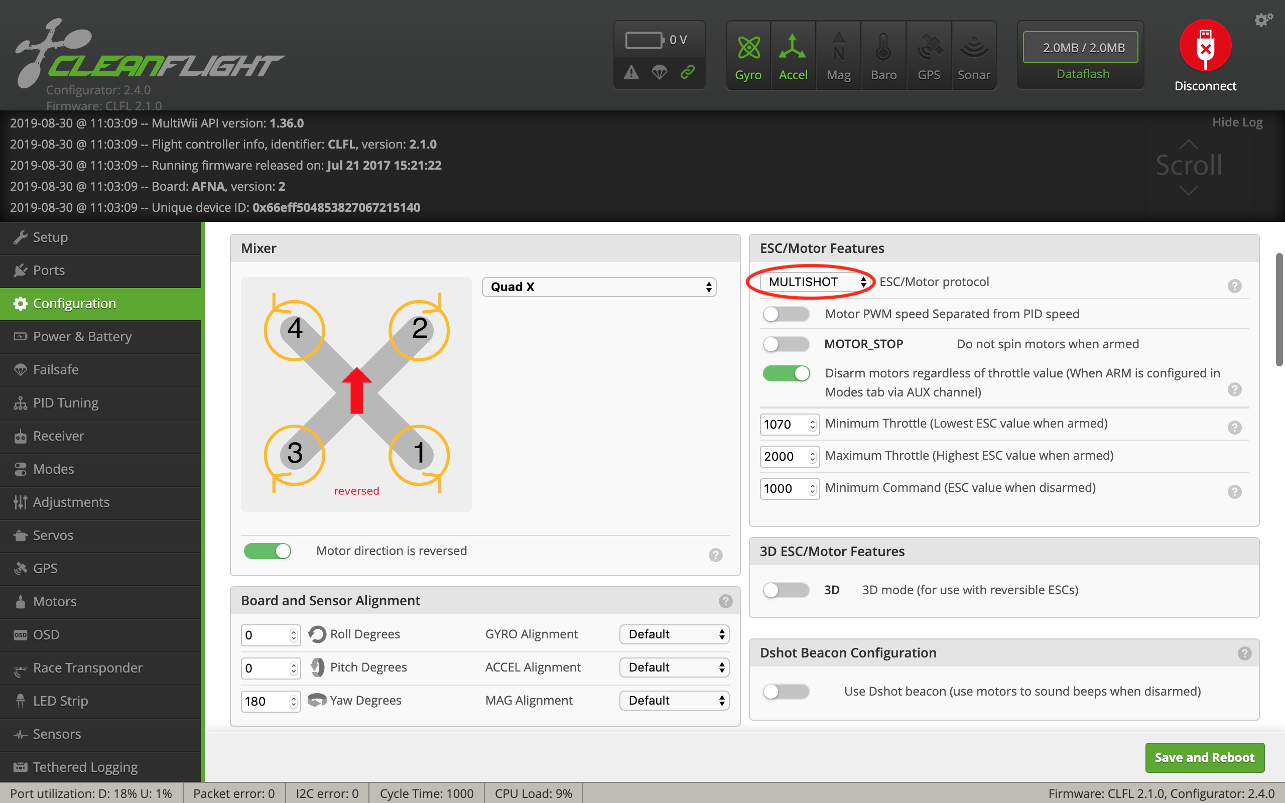
- Set the Minimum Throttle to 1100.

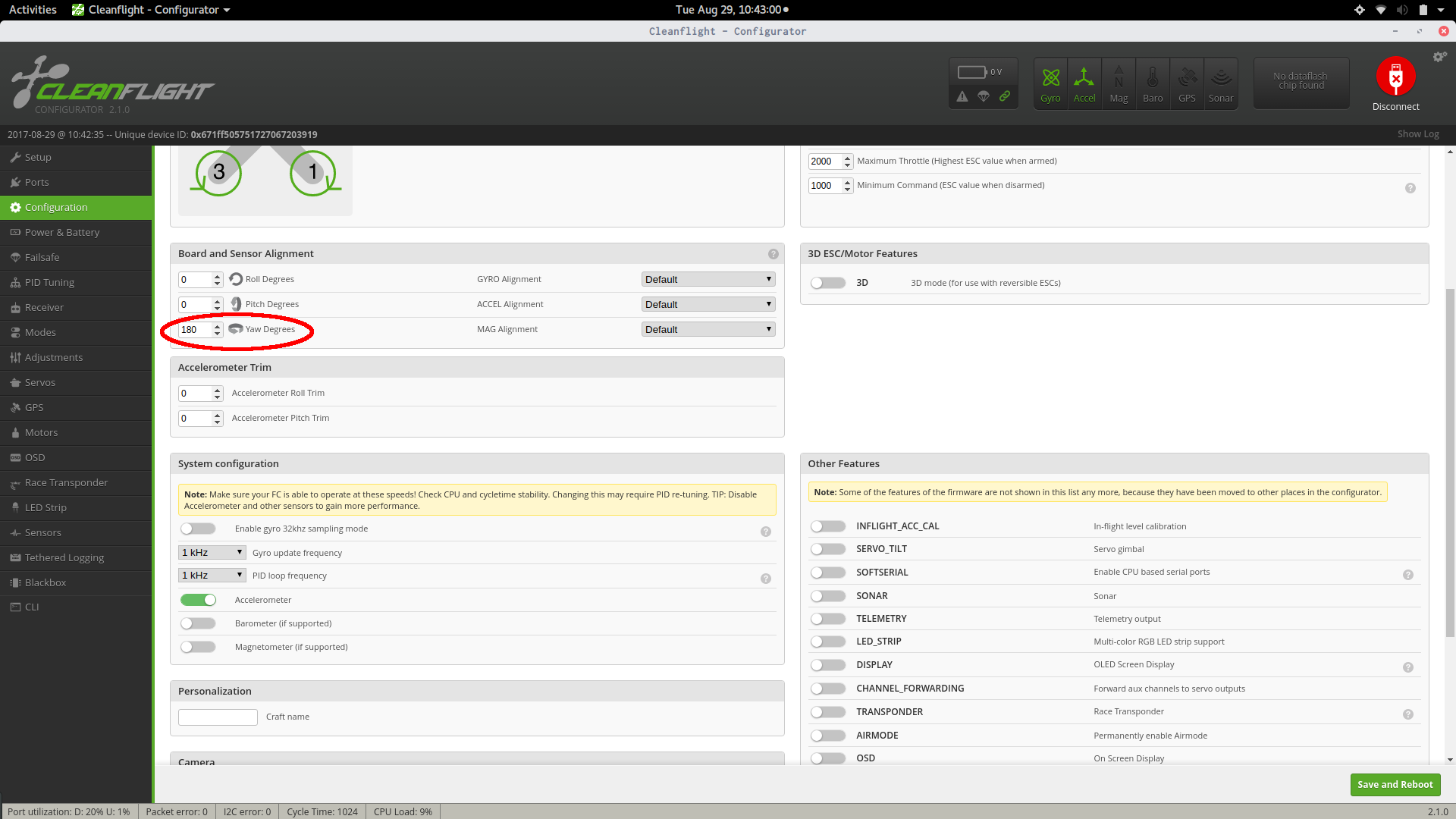
- Flip the yaw by 180° (because the FC is rotated by 180° when attached to the drone frame).
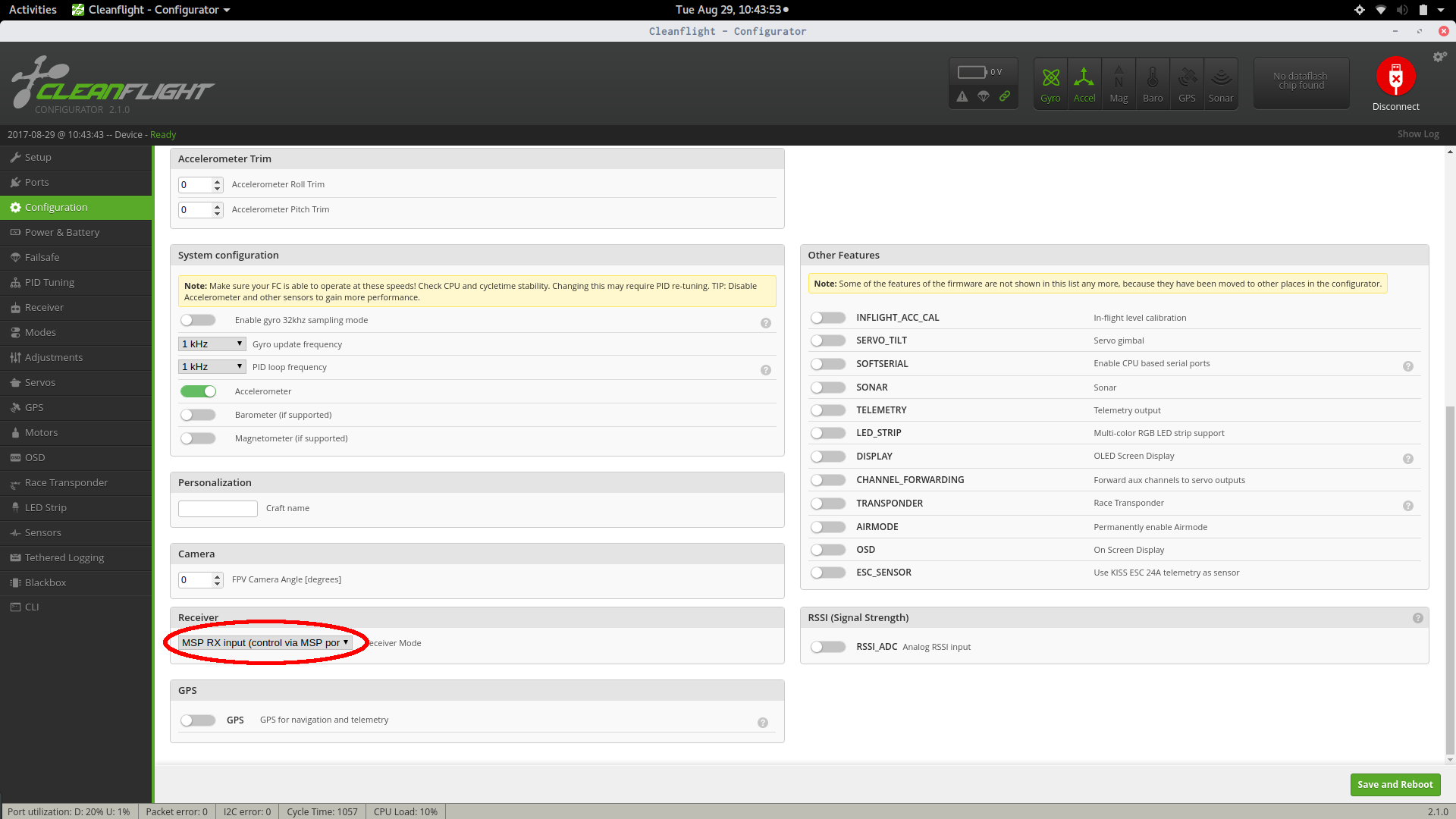
- Change the receiver to “MSP RX input” (by default it is configured to receive data from an RC receiver, but we want it to take commands over MSP).
- Finally, click “Save and Reboot.”
On the configuration page, Cleanflight might show that the direction of your motors are reversed. This is a UI bug and can be ignored. You will ensure that your motors are spinning in the correct direction in later steps.
“Modes”
✎Modified 2020-09-01 by Garrett Warren
The FC needs to be in Angle mode for its entire available range - not just the range of acrobatic mode.
Go to the “Modes” tab on the left side of cleanflight
- Under the “Angle” option, click “Add Range”.
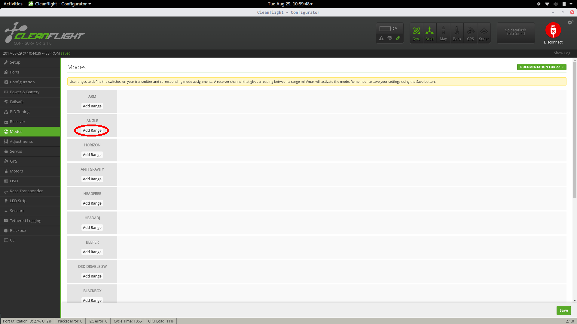
- Drag the sliders so that the range spans from 900 to 2100 (i.e. entire range).


- Finally, click “Save”.
PID Tuning
✎Modified 2020-09-01 by Garrett Warren
The FC PID parameters need to be changed to work better with our drone. Go to the “PID Tuning” tab. Change the “ROLL” and “PITCH” PID terms to match the image. For reference: Roll should be (Proportional: 60, Integral: 40, Derivative: 50, RC Rate: 1.00, Super Rate: 0.00, Max Vel: 200). Pitch should be (Proportional: 60, Integral: 40, Derivative: 50, RC Rate: curly bracket, Super Rate: 0.00, Max Vel: 200). Change angle limit to 50. Finally, click “Save”.

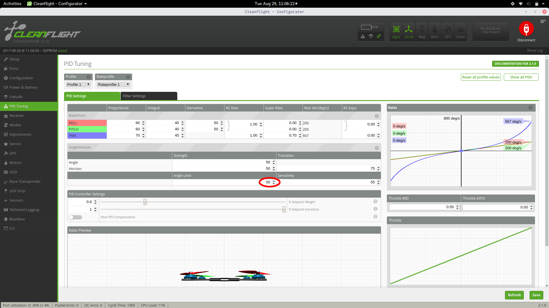
Double check that all of the settings in cleanflight match up to the ones above. Make sure to save the settings when possible.
Verify
✎Modified 2020-08-06 by Garrett Warren
To make sure that the settings were properly saved, you will verify just one of the changes.
-
navigate to the configuration tab
-
Scroll down to box that’s labelled “Receiver”
-
Make sure the input says “MSP RX Input”
Connecting the ESCs to the Flight Controller
✎Modified 2020-08-06 by Garrett Warren
Now that the FC has been configured, it can be connected to the ESCs via the PWM wires (i.e. the white and black wires on the ESCs). Take a moment not find the numbers 1-8 on the flight controller, adjacent to the pins that your soldered in. We will be connecting the PWM wires to number 1-4 because we have 4 motors. These numbers on the flight controller indicate which PWM wire should be connected to which set of pins on the flight controller. For example, in the image below, motor 1 is in the bottom right; therefore you will take the PWM wire from the ESC connected to the motor in the bottom right of your drone, and connect this to the pins labelled 1 on the flight controller.
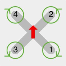
Where the red arrow indicates the front direction of the drone. Recall that for your drone, the FC is on the front and the camera is on the back.
There is a correct way to connect an ESC to the Flight Controller. Make sure the white wire of the ESC signal wire pair is facing toward the board, and the black wire is facing away.

1) Plug each PWM wire into its corresponding ESC signal wire pair.
Test the Motors
✎Modified 2019-10-21 by nkumar15-brown-university
With the ESCs connected to the FC, your drone’s motors can be tested. In this section, you will verify that the motors are spinning correctly.
Remove Propellors
✎Modified 2020-08-06 by Garrett Warren
Make sure no propellers are attached to your drone’s motors! You will be spinning the motors and you don’t want your drone to fly off your desk!
Launch Cleanflight
✎Modified 2020-08-06 by Garrett Warren
- Open up Cleanflight on your base station.
Connect your drone
✎Modified 2020-08-06 by Garrett Warren
-
Plug your drone’s FC into a computer (via the USB to micro USB cable)
-
Press connect in the top right corner of Cleanflight. (You won’t need to do this if “autoconnect” was selected)
-
Plug the battery into your drone.
Navigate to Motors tab
✎Modified 2020-08-06 by Garrett Warren
Go to the Motors tab in Cleanflight. Read the safety notice and check the box that says “I understand the risks, propellers are removed - Enable motor control”.
Test each motor
✎Modified 2020-08-06 by Garrett Warren
-
Slowly spin up the first motor by slowly dragging the 1 slider up
-
Use the motors diagram to verify that:
-
the correct motor spins. If the correct motor does not spin, reconnect the ESC wires to the FC in the correct order.
-
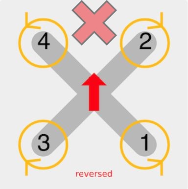
the motor spins in the correct direction. If the motor spins in the incorrect direction, take note and you will correct it later on. Read the following Remark and Note before continuing.
One way to find out which direction the motor is spinning is to put a piece of tap on the motor to create a flap. Then, use a pencil or other object and touch it to the tape while the motor is spinning to see which direction it is pushed.
DO NOT follow the incorrect motors diagram. If Cleanflight shows the incorrect motors diagram, then ignore it - the diagram is a UI bug and does not affect the spin directions of the motors.
Repeat this process for all of the motors.
Change the Motor Directions
✎Modified 2020-08-06 by Garrett Warren
Power your drone off by disconnecting the power supply.
For each motor that is spinning in the incorrect direction:
-
Disconnect any 2 of the 3 ESC pad wires from the motor, e.g. disconnect the red and yellow ESC pad wires from their corresponding motor wires. Keep track of which wires used to be connected together.
-
Swap the connections, e.g. plug the socket bullet connector of the red ESC pad wire into the plug bullet connector of the motor wire previously connected to the yellow ESC pad wire and vice-versa.
Verify
✎Re-connect a power supply to your drone and check that the motors are now spinning in the correct direction. If not, repeat the swapping process.
Calibrate the ESCs
✎Modified 2020-08-06 by Garrett Warren
By this point, your drone’s FC should be able to spin up each of the 4 motors. This is possible because the FC is sending PWM signals to each of the 4 ESCs, which in turn sends electrical signals to each of the 4 motors.
A PWM signal is a signla that communicates at how much RPM an ESC should spin a motor. For example, the PWM signal “1000” might correspond to 2300 RPM.
However, note that your drone has not 1, but 4 ESCs - which may not all have the same PWM-to-RPM understanding. For example, ESC 1 might think the PWM signal “1100” from the FC means 2300 RPM while ESC 2 might think the PWM signal “1000” means 2300 RPM.
The solution to this problem is to calibrate the ESCs with the FC. In this context, calibration means getting all the ESCs to have the same PWM-to-RPM understanding from the FC. In this section, you will calibrate your ESCs.
Note that symptoms of no calibration include: scorching hot motors, a drone that lifts to one side during flight, motors that appear to spin at different speeds.
Remove propellors
✎Modified 2020-08-06 by Garrett Warren
Make sure no propellers are attached to your drone’s motors!
Disconnect Power
✎Modified 2020-08-06 by Garrett Warren
Unplug the battery from your drone.
Launch Cleanflight
✎-
On your base station, open cleanflight
-
Connect the FC to a computer and click “Connect” in the top right of the screen
Navigate to the Motors tab
✎Modified 2020-08-06 by Garrett Warren
-
Go to the Motors tab on the left side of Cleanflight.
-
Read the safety notice and check the box that says “I understand the risks, propellers are removed - Enable motor control”.
Calibrate
✎Modified 2020-08-06 by Garrett Warren
-
Drag the master slider up to full. All 4 motor sliders should automatically move up to full accordingly (e.g. 2000).
-
Plug the battery into your drone.
The ESCs will make an interesting set of sounds, kind of like music. If they do not, stop and try the previous steps again.
-
After the music stops, drag the master slider to the bottom of the bar. Correspondingly, all 4 motor sliders should automatically be at the bottoms of their bars (e.g. 1000). The motors will make another set of sounds.
-
After the sounds stop, spin up each motor and verify it is spinning in the correct direction (i.e. according to the motors diagram in this doc).
-
Make sure the motors spin in the correct direction, i.e. according to the motors diagram in this doc.
-
When you connect the drone to power, the ESCs should make a “boop boop boop” sound, followed by a “beep BEEEEEP” sound.