Part 2: IR Sensor Instructions
✎Modified 2020-10-18 by sageshoyu
Expected Time: 2 hours
Solder Pins to the ADC
✎Modified 2020-08-05 by Garrett Warren
Identify the top and bottom
✎Modified 2020-08-06 by Garrett Warren
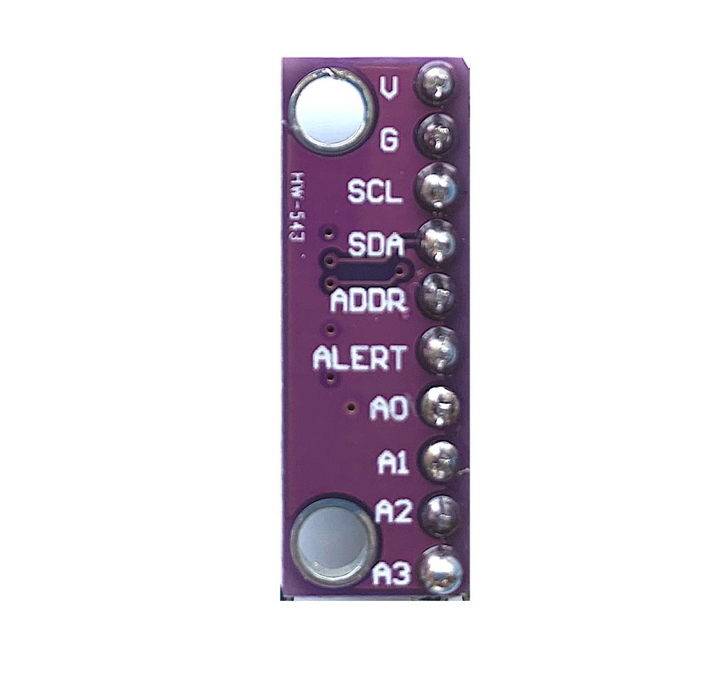
The top of the ADC has the labels near the holes, “V,” “G,” “SCL,” etc.
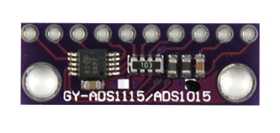
The bottom of the ADC says “ADS1115/ADS1015”
Insert pins
✎Modified 2020-08-05 by Garrett Warren
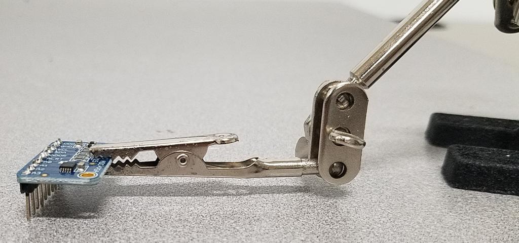
Insert the short ends of the pins into the holes in the bottom of the ADC and clamp the ADC with the helping hand as shown in the image below.
The ADC shown is from a previous hardware version. For your ADC, the helping hands will be on the left side and the pins will be on the right
Solder
✎Modified 2020-09-21 by Garrett Warren
Solder the pins on the top of the ADC using the through-hole soldering technique
Solder the ADC to the Pi Hat
✎Modified 2020-09-21 by Garrett Warren
Detach the Pi Hat from the Pi.
✎Modified 2020-08-05 by Garrett Warren
Gently lift the Pi Hat near the pin header to detach.
Solder the ADC to the Pi Hat
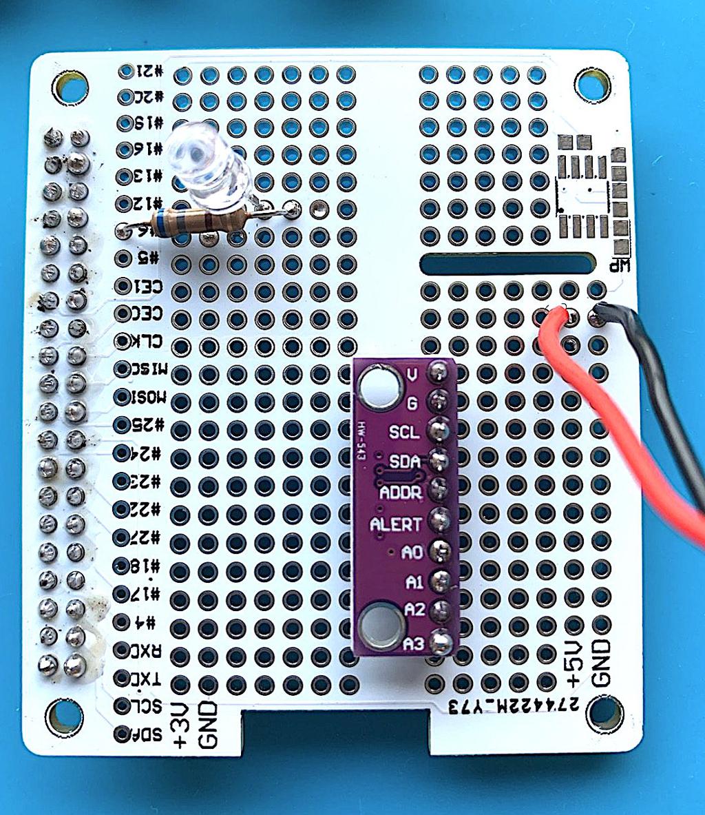
✎Following the image below, insert the ADC into front of the Pi Hat. Then, flip the Pi Hat over so you can solder the pins on the back of the Pi Hat using the through-hole soldering technique
Be sure to solder the ADC to the correct location on the Pi Hat. Use the location of the slot in the Pi Hat to help you align the ADC.

Solder the ADC wires
✎Modified 2020-09-21 by Garrett Warren
Following the diagram below, insert a wire into the correct hole on the front of the Pi Hat. Then, flip the Pi Hat over to solder the wire on the back of the Pi Hat using the through-hole soldering technique.
Recall that the Pi Hat is a breadboard, so it has rails. The wires you solder do not need to go into exact holes; each wire just needs to go into a hole on the same rail as its corresponding ADC pin. You can look at the back of the Pi Hat and see the metal connections between holes. You can also do a connectivity check with the multimeter if you have doubts about which holes are connected.
-
Use a small piece of red wire to connect the V pin of the ADC to the 5V rail.
-
Use a small piece of black wire to connect the G pin of the ADC to the the GND rail
-
Use a small piece of blue wire to connect the SCL pin of the ADC to the hole labelled SCL on the Pi Hat
-
Use a small piece of green wire to connect the SDA pin of the ADC to the hole labelled SDA on the Pi Hat
For the wires, we use the colors: red, black, green, and blue. However, any color wires will work.

Do a connectivity check on the Pi Hat; verify:
-
There is NO electrical connection (short) between the 5V and GND rails.
-
There is NO electrical connection (short) between the SCL and SDA wires
-
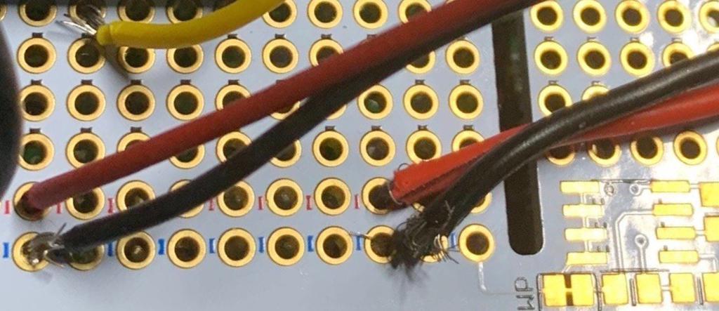
There are NO stray wire strands that are connecting adjacent pins, especially between 5V and GND (see image below)
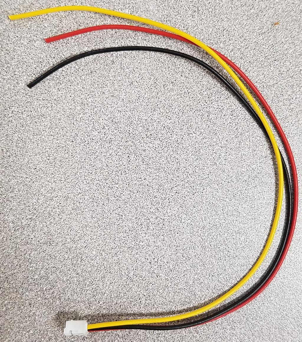
Prep the IR Sensor Wire
✎Modified 2020-08-05 by Garrett Warren
Trim
✎Modified 2020-08-05 by Garrett Warren
Cut the black plastic piece off the end of the IR sensor cable

Strip and Tin
✎Modified 2020-08-05 by Garrett Warren
-
Strip about 5mm off of the newly-exposed ends of the IR sensor wire
-
Twist and Tin the IR sensor wires. Do not put too much solder, as the wires must fit through the holes in the Pi Hat
Solder the IR Sensor Wires
✎Modified 2020-08-05 by Garrett Warren
Solder the IR Sensor Wires to the Pi Hat
✎Modified 2020-08-05 by Garrett Warren
Following the diagram below, insert a wire into the correct hole in the front of the Pi Hat. Then, flip the Pi Hat over to solder the wire on the back of the Pi Hat using the through-hole soldering technique.
-
Solder the red IR Sensor Wire to the 5V rail
-
Solder the black IR Sensor Wire to the GND rail
-
Solder the yellow IR Sensor Wire to any hole in the same row as A0 on the ADC

Do a connectivity check on the Pi Hat; verify:
- There is NO electrical connection (short) between the 5V and GND rails.
Reattach the Pi Hat to the Pi
✎Modified 2020-08-06 by Garrett Warren
Reattach the Pi Hat to the Pi by aligning the GPIO pins with the pin header and pressing down. Refer to part 1 for detailed instructions on how to attach the Pi Hat.