Part 1: Raspberry Pi and Power Distribution Overview
✎Modified 2020-10-18 by sageshoyu
Preface
✎Modified 2020-07-21 by Garrett Warren
In this first part of the build, you will create a circuit to provide power to the Raspberry Pi from the battery. You will make the circuit connections using the soldering skills that you’ve gained from the Soldering Module.
First, we will reintroduce you to the components that you will be working with. Then, you will do some preliminary tasks that will run in the background. As those tasks are running, you will go through the first portion of the build.
Required Materials
✎Modified 2020-08-31 by Garrett Warren
- Part : Quantity
- Battery : 1
- Battery Charger : 1
- Battery Charging Adapter : 1
- Power Distribution Board : 1
- Battery Eliminator Circuit : 1
- Pi Hat : 1
- XT60 Connector : 1
- Soldering Tools : 1
- Raspberry Pi : 1
- Heat Sinks: 1 set
- Micro SD Card : 1
- Base Station : 1
- Micro SD Card Reader : 1
- LED : 1
- Resistor : 1
Detailed Hardware Descriptions
✎Modified 2020-08-05 by Garrett Warren
Battery
✎Modified 2020-08-05 by Garrett Warren
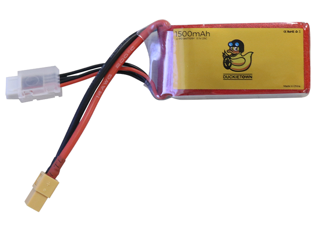
The Battery on your drone is a 1500mAh 3S 20C LiPo Battery. Let’s go over what all that means.
Capacity
The unit milliAmp hour, or mAh, is a measure of how much charge a battery can hold. The higher this number is, the more charge the battery can hold; therefore, the battery will “last” longer and your drone will fly for a longer time without needing to be recharged.
Structure
A Lithium-ion polymer (LiPo) battery is made up of one or more LiPo cells. Each cell has a voltage of 3.7 V when it is discharged, and 4.2 V when it is charged. The cells in your battery are connected in series, so that the voltages add together to get a total of 11.1 V when discharged, and 12.6 V when charged. There are three cells connected in series in your battery, so it is a 3S battery.
Current Output
The “C” rating of a LiPo Battery determines how much current the battery can deliver. The maximum current current draw is equal to the battery’s C rating multiplied by the battery’s capacity. For the drone’s 1500mAh 20C batteries, the maximum current draw is 1500mAh x 20C = 30A.
Precautions
Review the safety information on the battery. Take the proper precautions when using, storing, or charging is very important to keeping the battery safe. Only store the battery at room temperature and out of direct sun light. Do not discharge a battery below 10.5 V. Never leave the battery charging unattended. Unplug the battery once it is fully charged.
Power Distribution Board (PDB)
✎Modified 2020-08-05 by Garrett Warren

The Power Distribution Board is used to distribute power from the battery to electrical components of the drone. The PDB an example of Printed Circuit Board (PCB), which is a circuit board that has connections within its structure. For the PDB, the internal wiring connects all of the positive (+) pads together, and all of the negative (-) pads together; this allows for the battery to be connected to one set of positive and negative pads, and all of the other pads receive power.
BEC
✎Modified 2020-08-05 by Garrett Warren

The Battery Eliminator Circuit, or BEC, solves the issue that arises from different electrical components requiring different supply voltages. In the case of the drone, the LiPo battery used for outputs around 12V; this is the required voltage for the motors, but not for the Raspberry Pi, which requires 5V. The Battery Eliminator Circuit eliminates the need to carry multiple batteries of different voltages by converting the 12V supply from the battery down to a 5V supply for the Pi.
Raspberry Pi
✎Modified 2020-08-05 by Garrett Warren

The Raspberry Pi, or, Pi, is a low-cost, single-board computer. The Pi is capable of running a full desktop operating system; you can use it as a computer similar to the one you’re using now. The Pi is used on the drone as the main computer that reads and processes all of the sensor data and user inputs, and then sends commands to the flight controller to control the drone motors. The drone would be able to fly without the Pi if a person had a remote controller to manually steer the drone. However, for the DuckieSky Drone, the person with a remote controller is replaced by software and sensors on the Pi. The Pi, as well as the sensors you will connect later, makes autonomous flight possible.
Pi Hat
✎Modified 2020-09-03 by Andrea Censi
The Pi hat is a special type of breadboard. One useful property of a breadboard is that it has rails. A rail is a sequence of holes that share an electrical connection:
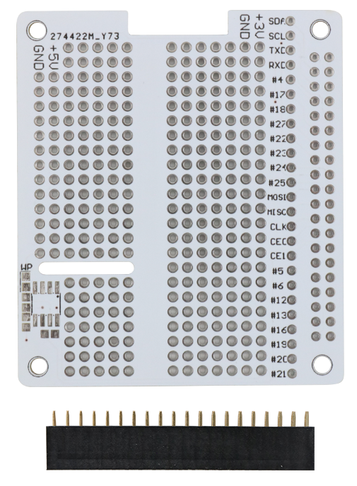

The rails are useful because every wire put on a rail will be electrically connected; this means that it does not matter into which hole along a rail a wire is inserted. This is useful for wire organization, and if a soldering mistake is made in one hole, an adjacent hole in the same rail can be used instead. Notice especially the long +5V and GND rails; we can use any of the holes in this rails to provide power to components. Also notice that there is a 3.3V rail, be sure not to mix this up with the 5V rail because electrical components will only work at the correct voltages.
Micro SD Card
✎Modified 2020-08-05 by Garrett Warren
The Micro SD card stores the operating system on the pi, as well as all of the software needed for autonomous flight.

Light Emitting Diode (LED)
✎Modified 2020-08-05 by Garrett Warren

An LED is a device that emits light as current flows through it; the color of the light is based on the material properties of the LED. An LED has a polarity, meaning that current can only flow through the device in one direction. If electricity flows in the wrong direction, the device will be damaged; be sure to double check the LED direction before soldering. The correct direction of flow is from the anode (the positive terminal) to the cathode (the negative terminal). You will be able to identify the anode because it has a longer terminal, as shown in the image.
Another property of an LED is that it has very little resistance. Recall that Ohms states that I = V / R. The resistance of an LED is so low that we can assume it is zero. Plug zero into the equation and we get an infinite amount of current. In reality, the current is limited by the power source. Since there is such little resistance with the LED, if we created a circuit with only this element, it would burn out from too much current, and the battery may be damaged.
Can you think of a way that we could limit the current passing through the LED?
If you thought of using a resistor, then you’re right!
Resistor
✎Modified 2020-07-21 by Garrett Warren
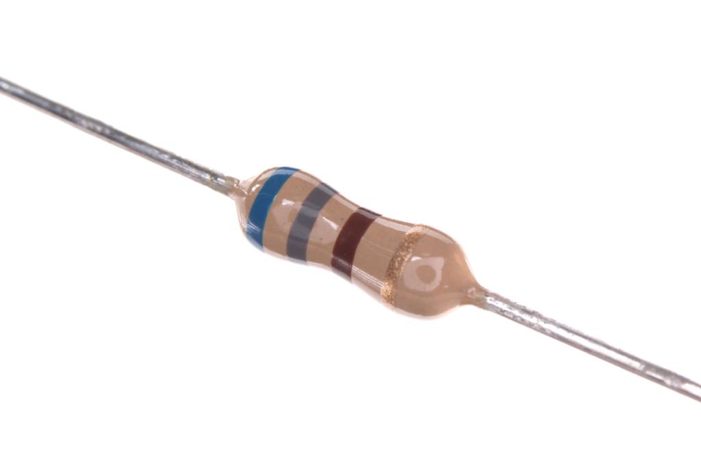
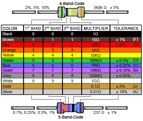
Resistors are passive elements that add resistance to a circuit. Each resistor has a specific resistance and a tolerance. To determine the resistance of a resistor, one must look up the color code of the colored bands on the resistor. The resistor in the image is 680 Ohms.
if you have poor eyesight or experience difficulty seeing colors, it is useful to ask a friend to read the colors they see and you can look up the colors on the chart.
XT60 Connector
✎Modified 2020-08-05 by Garrett Warren
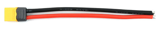
An XT60 connector cable is a component which provides power when a power source (e.g. battery) is connected to it. By soldering it to the PDB, the PDB will get power to distribute to other components.
Build Progress
✎Modified 2020-08-05 by Garrett Warren
You are going to create a circuit to provide power to the Pi. You will also create a simple circuit using an LED and resistor that will allow you to control the LED using the Raspberry Pi. Later in the course, you’ll learn how to write a script to turn the LED on and off, as well as vary its brightness!
After completing this section, your build will match the diagram below. Compare this diagram to the completed drone diagram to see how what you’re doing now fits into the final result.

The electricity flows from the battery, through the PDB to the BEC where the voltage is stepped down to 5V, then into the Pi Hat, and finally to the Pi and the LED.