Assembly - Duckiebot DB17
✎
Modified 2021-03-13 by duckietown
This page is for the DB17 configuration used in classes in 2017. The docker based software stack of 2018 is currently not guaranteed to work out of the box with the DB17 hardware configurations.
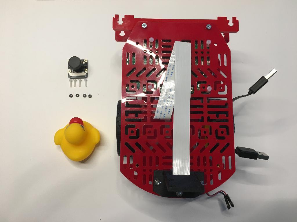
Duckiebot DB17 parts. The acquisition process is explained in Subsection 3.2.1 - DB17 Bill of materials.
A microSD card with the Duckiebot image already on it. This procedure is explained here.
Time: about 1-1.5 hours (45 minutes for an experienced Duckiebot builder).
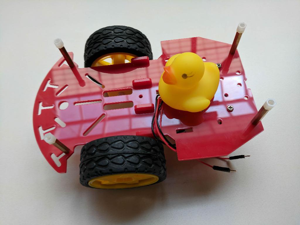
An assembled Duckiebot in configuration DB17.
There are several steps in this procedure. Many steps rely on previous ones, so make sure you perform them in order!
Assembly instructions (DB17-jwd)
✎
Modified 2021-03-13 by duckietown
Once you have received the parts and soldered the necessary components, it is time to assemble them in a Duckiebot. Here, we provide the assembly instructions for the configuration DB17-wjd.
Duckiebot DB17-wjd parts. The acquisition process is explained in Section 3.2 - Acquiring the parts for a DB17.
Having soldered the DB17-wjd parts. The soldering process is explained in Section 16.2 - Assembly instructions (DB17): soldering.
Having prepared the power cable. The power cable preparation is explained in Subsection 16.2.5 - Assembly instructions (DB17-jwd): power cable. Note: Not necessary if you intend to build a DB17-l configuration.
Time: about 30 minutes.
An assembled Duckiebot in configuration DB17-wjd.
The FAQ section at the bottom of this page may already answer some of you comments, questions or doubts.
This section is comprised of 14 parts. Each part builds upon some of the previous parts, so make sure to follow them in the following order.
- Part I: Motors
- Part II: Wheels
- Part III: Omni-directional wheel
- Part IV: Chassis standoffs
- Part V: Camera kit
- Part VI: Heat sinks
- Part VII: Raspberry Pi 3
- Part VIII: Top plate
- Part IX: USB Power cable
- Part X: DC Stepper Motor HAT
- Part XI: Battery
- Part XII: Upgrade to
DB17-w - Part XIII: Upgrade to
DB17-j - Part XIV: Upgrade to
DB17-d
Motors
✎Modified 2021-03-13 by duckietown
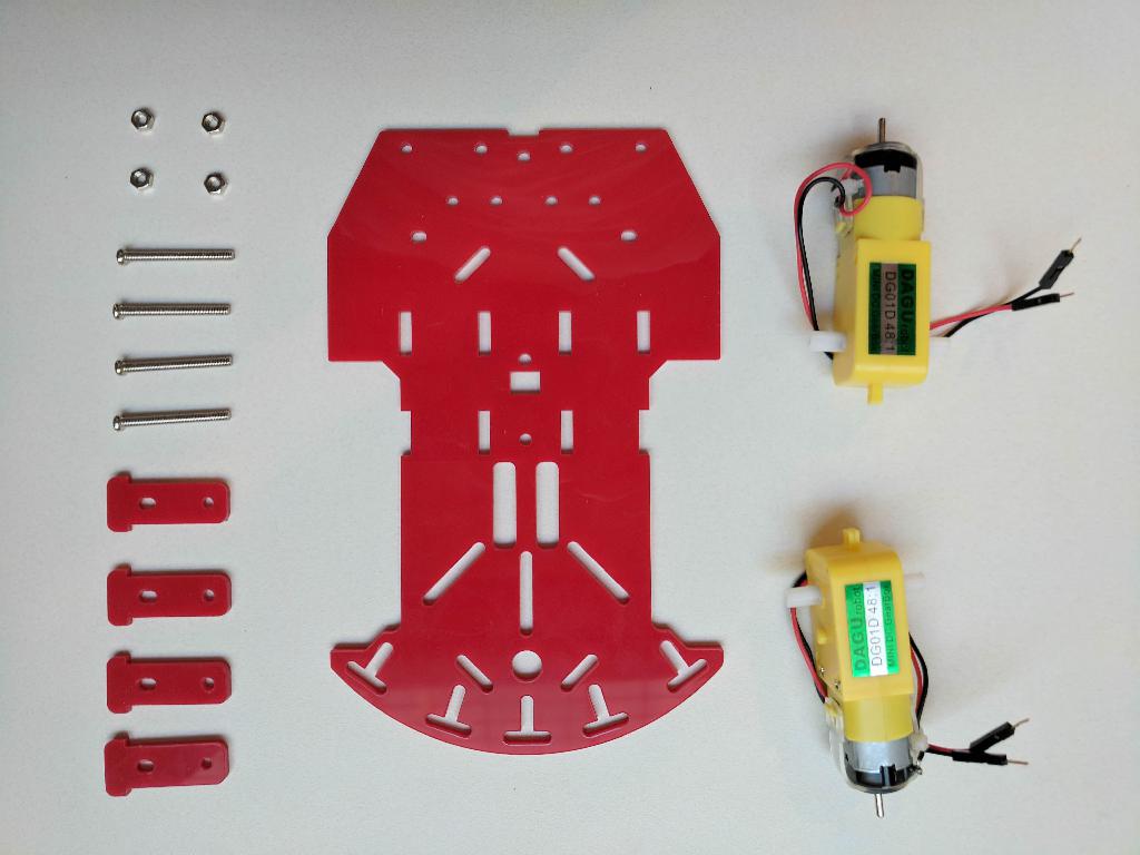
Open the Magician Chassis package and take out the following components:
- Chassis-bottom (1x)
- DC Motors (2x)
- Motor holders (4x)
- M3x30 screw (4x)
- M3 nuts (4x)
Figure 16.1 shows the components needed to complete this part of the tutorial.
Video tutorial
✎The following video shows how to attach the motors to the bottom plate of the chassis.

The video is at https://vimeo.com/236334401.
Step-by-step guide
✎Modified 2021-03-13 by duckietown
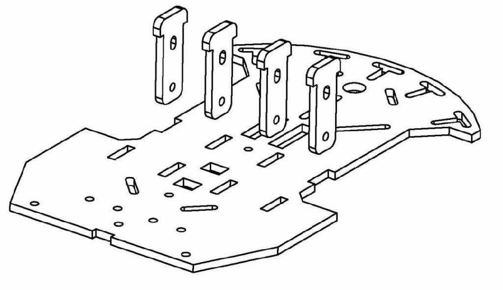
Step 1
✎Pass the motor holders through the openings in the bottom plate of the chassis as shown in Figure 16.3.
Step 2
✎Put the motors between the holders as shown in Figure 16.4.

Orient the motors so that their wires are inwards (i.e., towards the center of the plate).
Step 3
✎Use 4 M3x30 screws and 4 M3 nuts to secure the motors to the motor holders. Tighten the screws to secure the holders to the bottom plate of the chassis as shown in Figure 16.5.

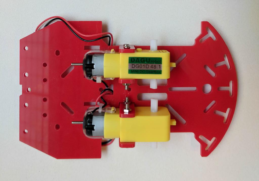
Check the outcome
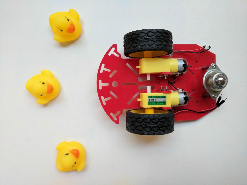
✎Figure 16.6 shows how the motors should be attached to the bottom plate of the chassis.
Wheels
✎Modified 2021-03-13 by duckietown
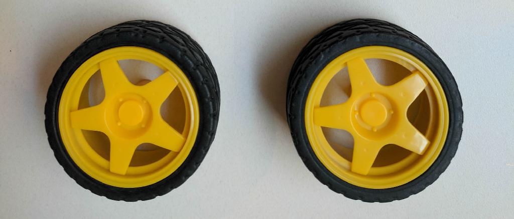
From the Magician Chassis package take the following components:
- Wheels (2x)
Figure 16.7 shows the components needed to complete this part of the tutorial.
Video tutorial
✎The following video shows how to attach the wheels to the motors.

The video is at https://vimeo.com/236334418.
Check the outcome
✎Figure 16.9 shows how the wheels should be attached to the motors.

Omni-directional wheel
✎Modified 2021-03-13 by duckietown
The Duckiebot is driven by controlling the wheels attached to the DC motors. Still, it requires a passive support on the back. In this configuration an omni-directional wheel is attached to the bottom plate of the chassis to provide such support.
From the Magician Chassis package take the following components:
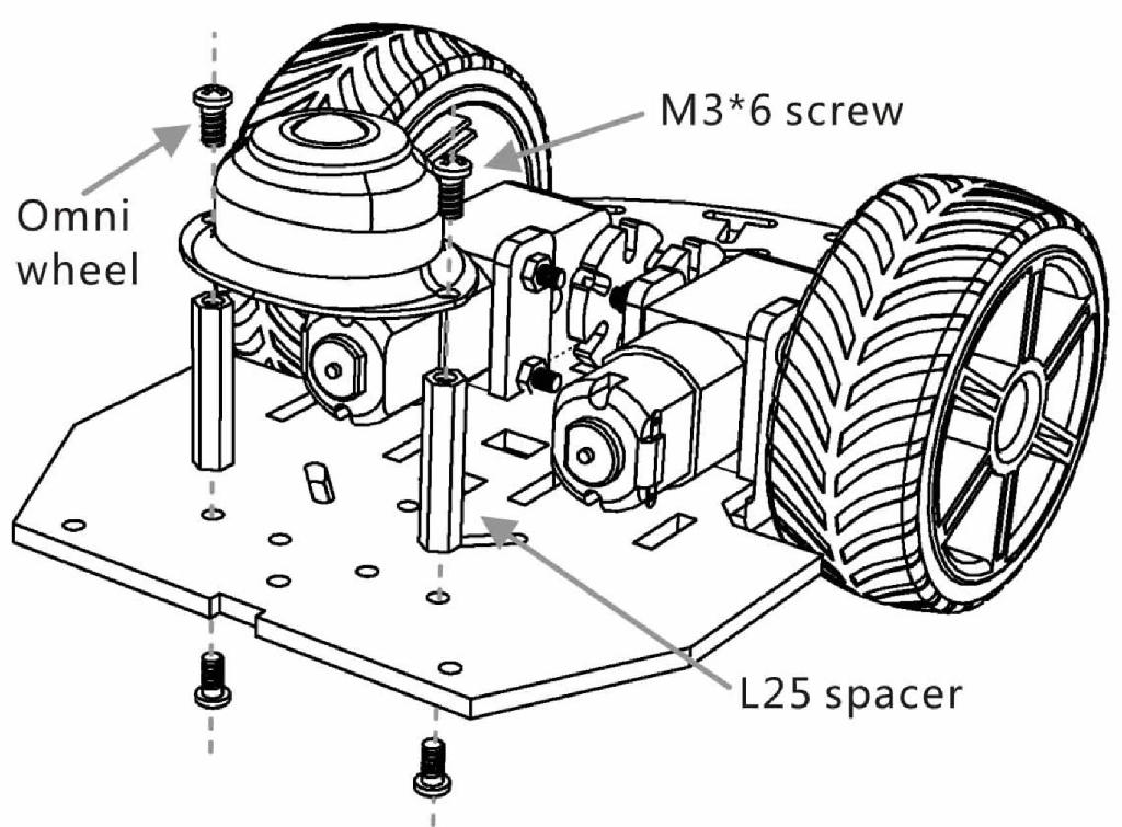
- Steel omni-directional wheel (1x)
- Long metal spacers (2x)
- M3x6 screws (4x)
Figure 16.10 shows the components needed to complete this part of the tutorial.

Video tutorial
✎The following video shows how to attach the omni-directional wheel to the bottom plate of the chassis.

The video is at https://vimeo.com/236334422.
Step-by-step guide
✎Step 1
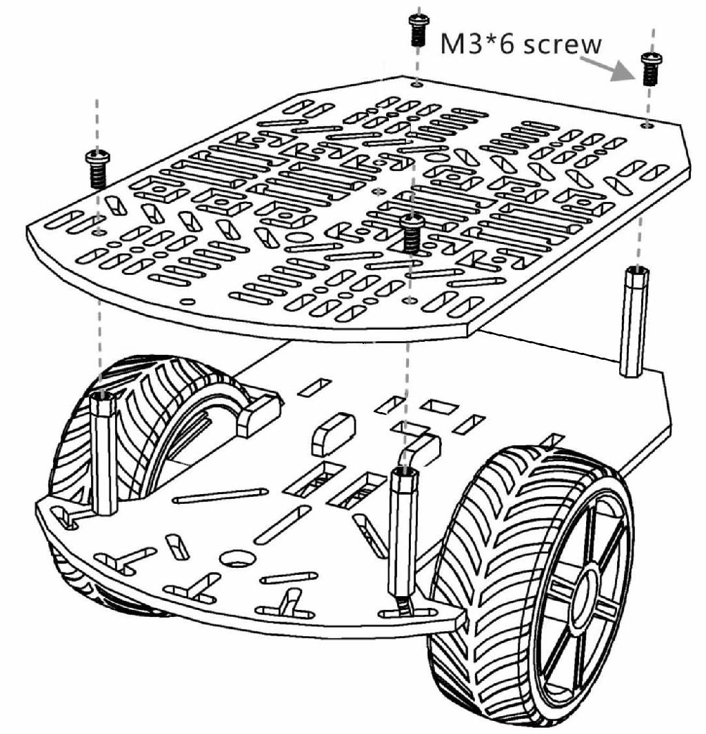
✎Secure the long spacers to the plate using 2 M3x6 screws and the omni-directional wheel to the spacers using also 2 M3x6 screws as shown in Figure 16.12.
Check the outcome
✎Figure 16.13 shows how the omni-directional wheel should be attached to the plate.
Chassis standoffs
✎Modified 2021-03-13 by duckietown
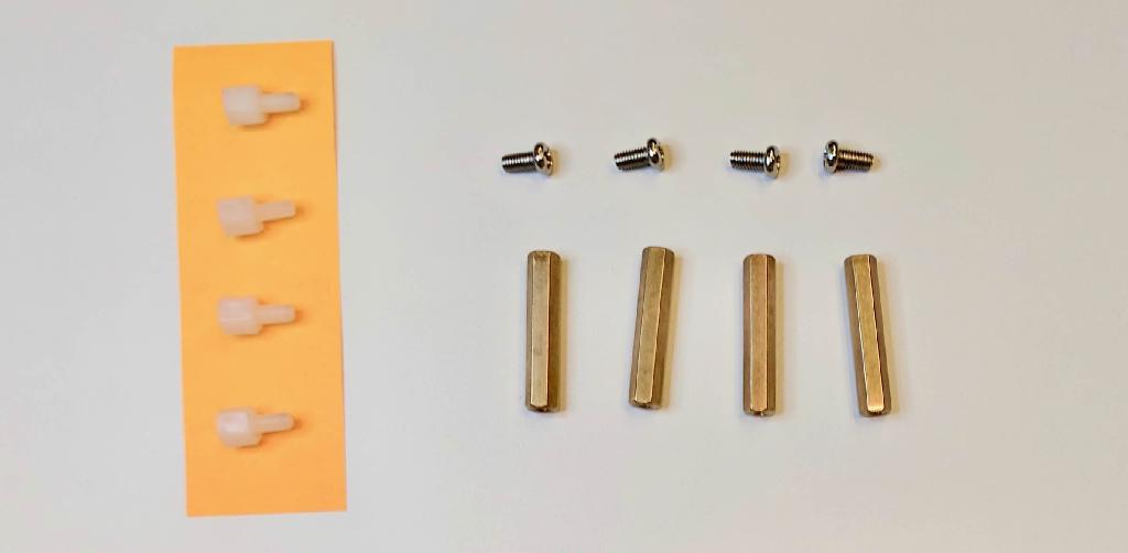
From the Magician Chassis package take the following components:
- Long metal spacers/standoffs (4x)
- M3x6 screws (4x)
From the Duckiebot kit take the following components:
- M3x5 nylon spacers/standoffs (4x)
Figure 16.14 shows the components needed to complete this part of the tutorial.
Video tutorial
✎The following video shows how to attach the standoffs to the bottom plate of the chassis.

The video is at https://vimeo.com/236334431.
Step-by-step guide
✎Step 1
✎Secure the long metal spacers to the bottom plate using 4 M3x6 screws as shown in Figure 16.16.
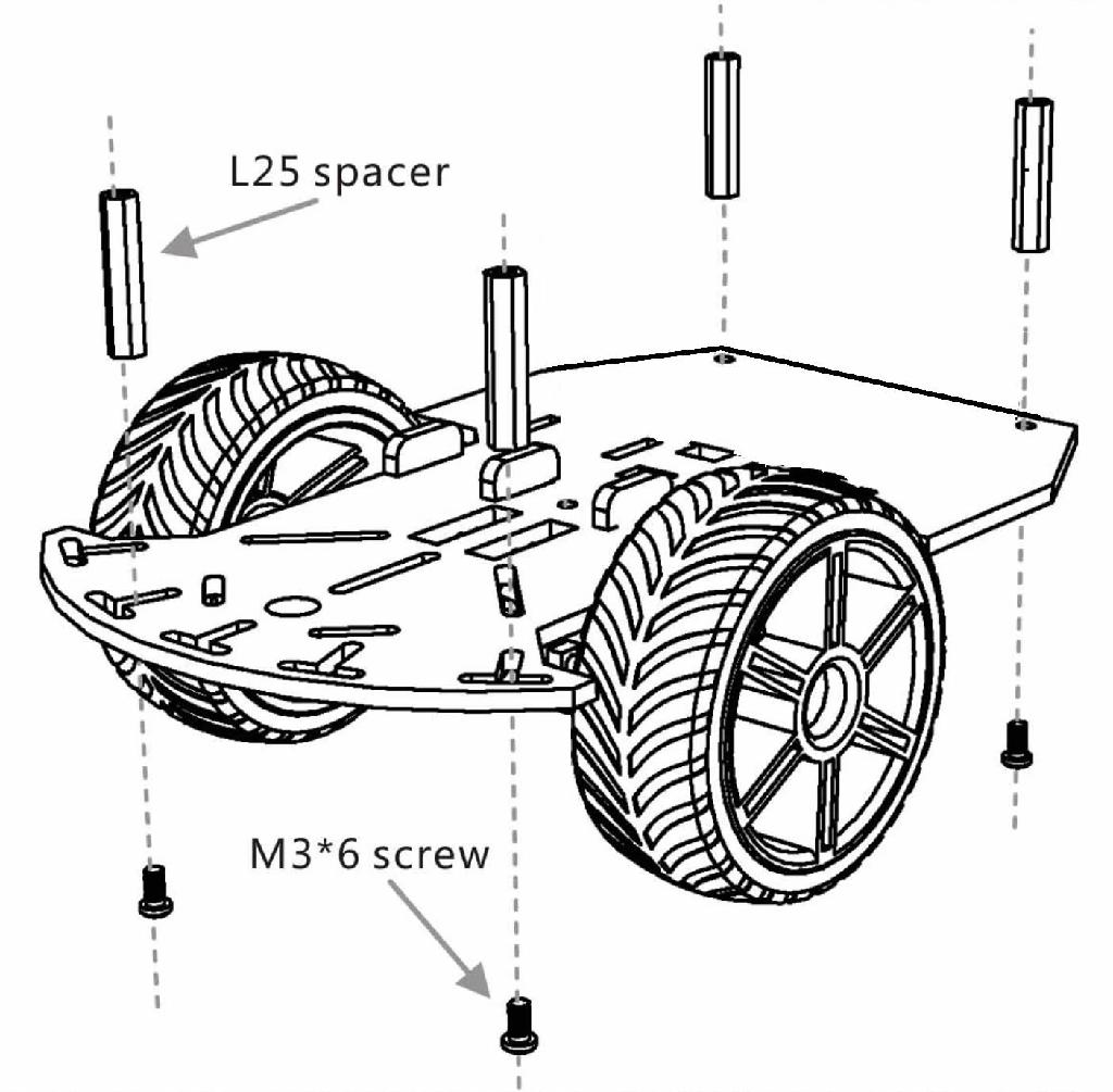
Step 2
✎Attach the 4 nylon standoffs on top of the metal ones.
Check the outcome
✎Figure 16.17 shows how the standoffs should be attached to the plate.
Camera kit
✎Modified 2021-03-13 by duckietown
From the Magician Chassis package take the following components:
- M3x10 flathead screws (2x)
- M3 nuts (2x)
From the Duckiebot kit take the following components:
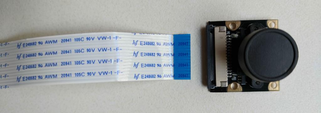
- Camera Module (1x)
- (Optional) 300mm Camera cable (1x)
- Camera mount (1x)
If you have camera cables of different lengths available, keep in mind that both are going to work. We suggest to use the longer one, and wrap the extra length under the Raspberry Pi stack.
Figure 16.18 shows the components needed to complete this part of the tutorial.
Video tutorial
✎The following video shows how to secure the camera to the top plate of the chassis.

The video is at https://vimeo.com/236334448.
Step-by-step guide
✎Step 1 (Optional)
✎If you do not have the 300mm Camera cable you can jump to Step 3.
If you do have the long camera cable, the first thing to do is removing the shorter cable that comes attached to the camera module. Make sure to slide up the black connectors of the camera port on the camera module in order to unblock the cable.
Step 2
✎Connect the camera cable to the camera module as shown in Figure 16.20.
Step 3
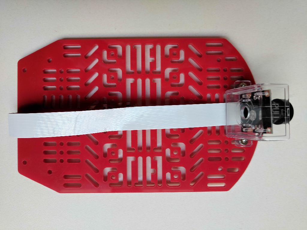
✎Attach the camera module to the camera mount as shown in Figure 16.21.
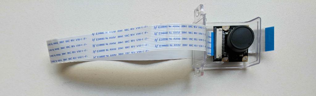
The camera is just press-fitted to the camera mount, no screws/nuts are needed.
Step 4
✎Secure the camera mount to the top plate by using the 2 M3x10 flathead screws and the nuts as shown in Figure 16.22.

Check the outcome
✎Figure 16.23 shows how the camera should be attached to the plate.
Heat sinks
✎Modified 2021-03-13 by duckietown
From the Duckiebot kit take the following components:
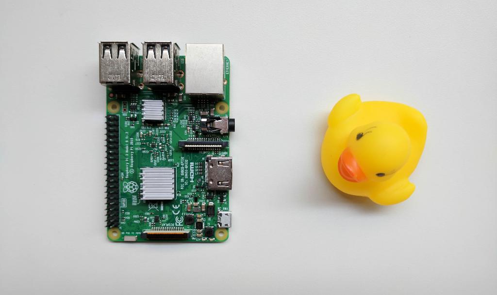
- Raspberry Pi 3 (1x)
- Heat sinks (2x)
- Camera mount (1x)
Figure 16.24 shows the components needed to complete this part of the tutorial.

Video tutorial
✎The following video shows how to install the heat sinks on the Raspberry Pi 3.

The video is at https://vimeo.com/236334458.
Step-by-step guide
✎Step 1
✎Remove the protection layer from the heat sinks.
Step 2
✎Install the big heat sink on the big “Broadcom”-labeled integrated circuit (IC).
Step 3
✎Install the small heat sink on the small “SMSC”-labeled integrated circuit (IC).
Check the outcome
✎Figure 16.26 shows how the heat sinks should be installed on the Raspberry Pi 3.
Raspberry Pi 3
✎Modified 2021-03-13 by duckietown
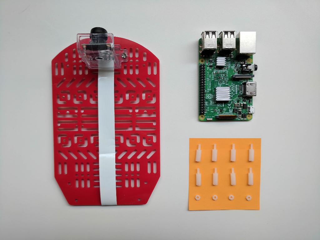
From the Magician Chassis package take the following components:
- Top plate (with camera attached) (1x)
From the Duckiebot kit take the following components:
- Raspberry Pi 3 (with heat sinks) (1x)
- M2.5x12 nylon spacers/standoffs (8x)
- M2.5 nylon hex nuts (4x)
Figure 16.27 shows the components needed to complete this part of the tutorial.
Video tutorial
✎The following video shows how to mount the Raspberry Pi 3 on the top plate of the chassis.

The video is at https://vimeo.com/236334461.
Step-by-step guide
✎Step 1
✎Mount 8 M2.5x12 nylon standoffs on the Raspberry Pi 3 as shown in Figure 16.29.

Step 2
✎Use the M2.5 nylon hex nuts to secure the Raspberry Pi 3 to the top plate as shown in Figure 16.30.
Check the outcome
✎Figure 16.31 shows how the Raspberry Pi 3 should be mounted on the top plate of the chassis.

Top plate
✎Modified 2021-03-13 by duckietown
From the Magician Chassis package take the following components:
- Bottom plate (with motors, wheels and standoffs attached) (1x)
- Top plate (with camera and Raspberry Pi 3 attached) (1x)
- M3x6 screws (4x)
Figure 16.32 shows the components needed to complete this part of the tutorial.

Video tutorial
✎The following video shows how to secure the top plate on top of the bottom plate.

The video is at https://vimeo.com/236334469.
Step-by-step guide
✎Step 1
✎Pass the motor wires through the openings in the top plate.
Step 2
✎Use 4 M3x6 screws to secure the top plate to the nylon standoffs (mounted on the bottom plate in Subsection 16.1.6 - Chassis standoffs) as shown in Figure 16.34.
Check the outcome
✎Figure 16.35 shows how the top plate should be mounted on the bottom plate.

USB Power cable
✎Modified 2021-03-13 by duckietown
The power cable preparation is explained in Subsection 16.2.5 - Assembly instructions (DB17-jwd): power cable.
DC Stepper Motor HAT
✎Modified 2021-03-13 by duckietown
From the Duckiebot kit take the following components:
- USB power cable (prepared in Subsection 16.2.5 - Assembly instructions (
DB17-jwd): power cable) (1x) - DC Stepper Motor HAT (1x)
- M2.5x10 Nylon screws (or M2.5x12 nylon standoffs) (4x)
Figure 16.36 shows the components needed to complete this part of the tutorial.
Video tutorial
✎The following video shows how to connect the DC Stepper Motor HAT to the Raspberry Pi 3.

The video is at https://vimeo.com/236334482.
Step-by-step guide
✎Step 1
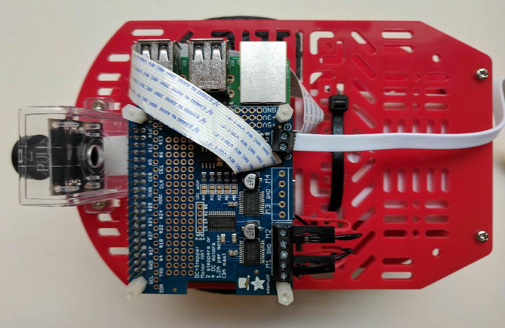
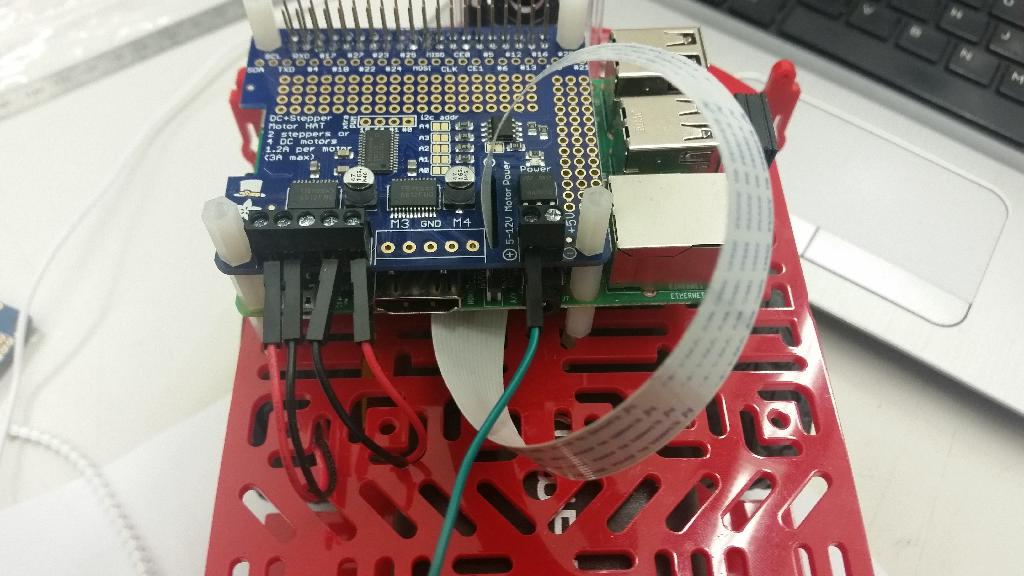
✎Connect the wires of the USB power cable to the terminal block on the DC Stepper Motor HAT labeled as
“5-12V Motor Power” as shown in Figure 16.38.
The black wire goes to the negative terminal block (labeled with a minus: -) and the red wire goes to the
positive terminal block (labeled with a plus: +).
Step 2
✎Pass the free end of the camera cable through the opening in the DC Stepper Motor HAT as shown in Figure 16.39.

Step 3
✎Connect the free end of the camera cable to the CAMERA port on the Raspberry Pi 3 as shown in Figure 16.40.

To do so, you will need to gently pull up on the black connector (it will slide up) to allow the cable to insert the port. Slide the connector back down to lock the cable in place, making sure it “clicks”.
Make sure the camera cable is inserted in the right direction! The metal pins of the cable must be in contact with the metal terminals in the camera port of the PI. Please be aware that different camera cables have the text on different sides and with different orientation, do not use it as a landmark.
Step 4
✎Attach the DC Stepper Motor HAT to the GPIO header on the Raspberry Pi 3. Make sure that the GPIO stacking header of the Motor HAT is carefully aligned with the underlying GPIO pins before applying pressure.
In case you are using a short camera cable, ensure that the camera cable does not stand between the GPIO pins and the the GPIO header socket before applying pressure.
Step 5
✎Secure the DC Stepper Motor HAT using 4 M2.5x10 nylon screws.
If you are planning on upgrading your Duckiebot to the configuration DB17-l, you can use 4 M2.5x12
nylon standoffs instead.
Step 6
✎Connect the motor wires to the terminal block on the DC Stepper Motor HAT as shown in Figure 16.41.
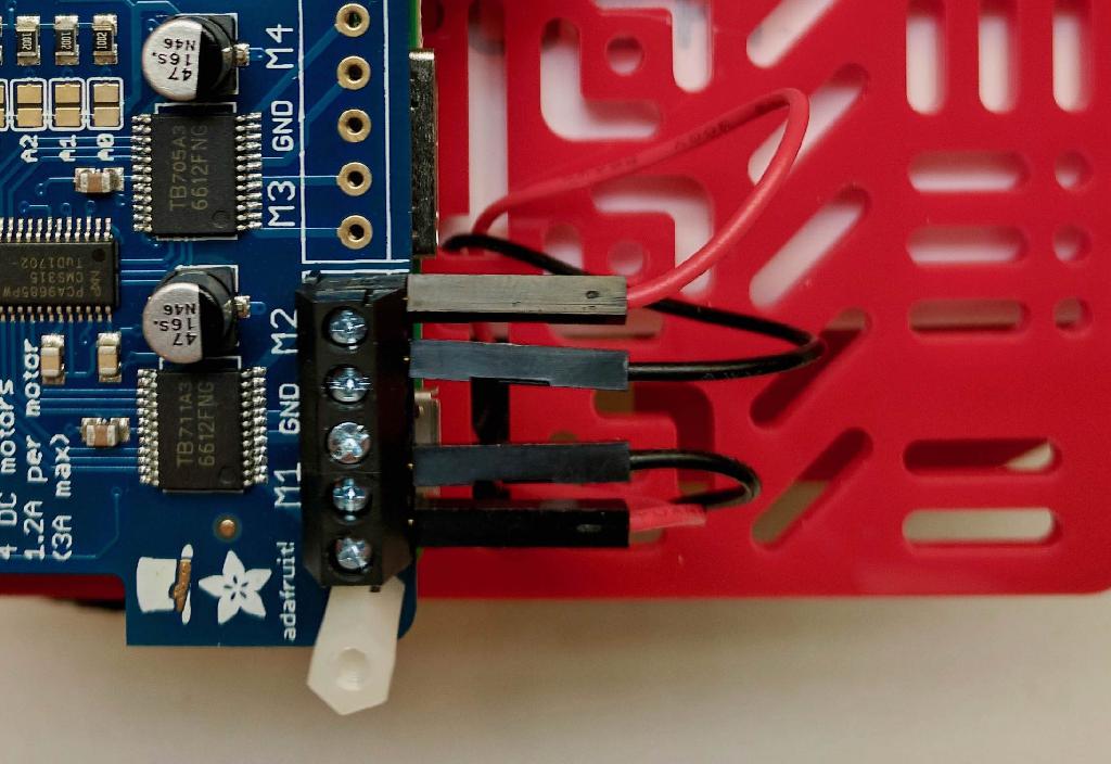
While looking at the Duckiebot from the back, identify the wires for left and right motor. Connect the left motor wires to the terminals labeled as M1 and the right motor wires to the terminals labeled as M2. This will ensure that the pre-existing software that we will later install on the Duckiebot will send the commands to the correct motors.
Check the outcome
✎Figure 16.42 shows how the DC Stepper Motor HAT should be connected to the Raspberry Pi 3.
Battery
✎Modified 2021-03-13 by duckietown
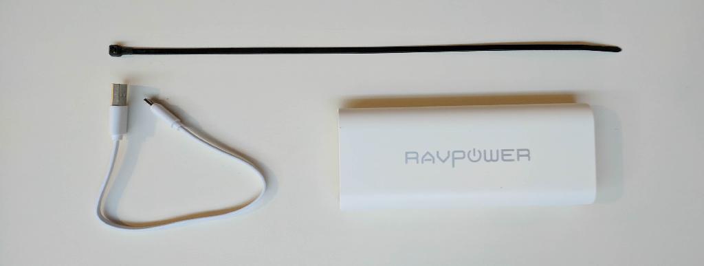
From the Duckiebot kit take the following components:
- Battery (1x)
- Zip tie (1x)
- Short micro USB cable (1x)
Figure 16.43 shows the components needed to complete this part of the tutorial.
Video tutorial
✎The following video shows how to add the battery to the Duckiebot and turn it on.

The video is at https://vimeo.com/236334493.
Step-by-step guide
✎Step 1
✎Pass the zip tie through the opening in the top plate.
Step 2
✎Slide the battery between the two plates. Make sure it is above the zip tie.
Step 3
✎Push the free end of the zip tie through the opening in the top plate.
Step 4
✎Tighten the zip tie to secure the battery.
Step 5
✎Connect the short micro USB cable to the Raspberry Pi 3.
Step 6
✎Connect the short micro USB cable to the battery.
Step 7
✎Connect the USB power cable to the battery.
Step 8
✎Make sure that the LEDs on the Raspberry Pi 3 and the DC Stepper Motor HAT are on.
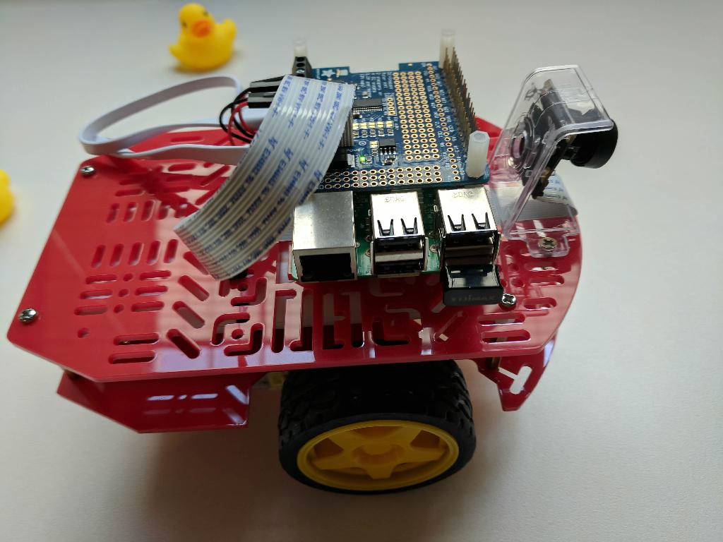
Check the outcome
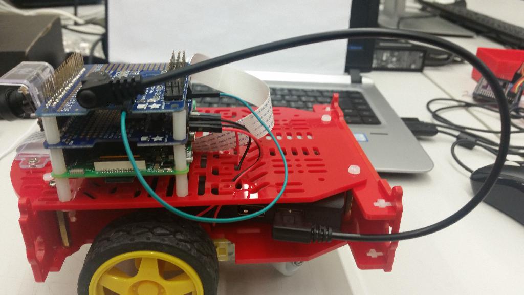
✎Figure 16.45 shows how the battery should be installed on the Duckiebot.

Upgrade to DB17-w
✎
Modified 2021-03-13 by duckietown
This upgrade equips the Duckiebot with a secondary, faster, Wi-Fi connection, ideal for image streaming.
The new configuration is called DB17-w.
Figure 16.46 shows the components needed to complete this upgrade.

Instructions
✎- Insert the USB WiFi dongle into one of the USB ports of the Raspberry Pi.
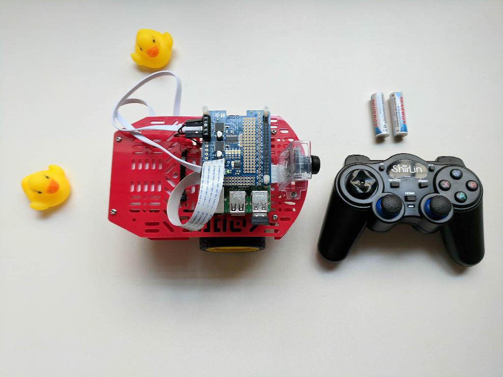
Upgrade to DB17-j
✎
Modified 2021-03-13 by duckietown
This upgrade equips the Duckiebot with manual remote control capabilities. It is particularly
useful for getting the Duckiebot out of tight spots or letting younger ones have a drive, in
addition to providing handy shortcuts to different functions in development phase.
The new configuration is called DB17-j.
Figure 16.48 shows the components needed to complete this upgrade.
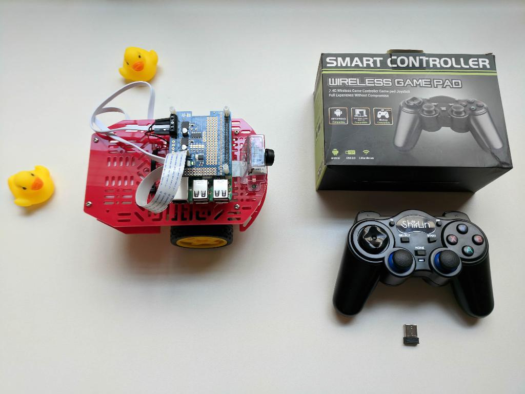
The joystick comes with a USB receiver (as shown in Figure 16.48).
Instructions
✎- Insert the USB receiver into one of the USB ports of the Raspberry Pi.
- Insert 2 AA batteries on the back side of the joystick.
- Turn on the joystick by pressing the
HOMEbutton. Make sure that the LED above theSELECTbutton is steady.
Upgrade to DB17-d
✎
Modified 2021-03-13 by duckietown
This upgrade equips the Duckiebot with an external hard drive that is convenient for storing
videos (logs) as it provides both extra capacity and faster data transfer rates than the microSD
card in the Raspberry Pi 3. Moreover, it is easy to unplug it from the Duckiebot at the end of the
day and bring it over to a computer for downloading and analyzing stored data.
The new configuration is called DB17-d.
Figure 16.50 shows the components needed to complete this upgrade.
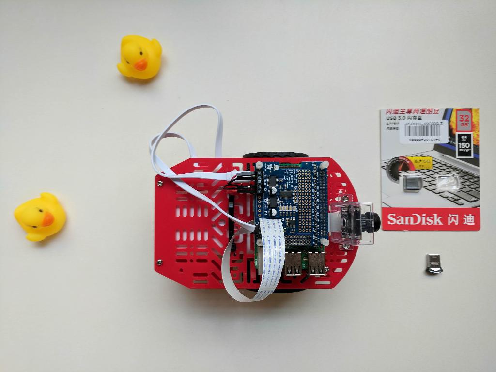
Instructions
✎- Insert the USB drive into one of the USB ports of the Raspberry Pi.
- Mount your USB drive.
TODO: re-add instructions from 2017 Duckiebook version.
FAQ
✎Modified 2021-03-13 by duckietown
If we have the bumpers, at what point should we add them?
You shouldn’t have the bumpers at this point. The function of the bumpers is to keep the LEDs in place, i.e., they belong to DB17-l configuration. These instructions cover the DB17-wjd configurations. You will find the bumper assembly instructions in Section 16.3 - Bumper Assembly.
Yeah but I still have the bumpers and am reading this page. So?
The bumpers can be added after the Duckiebot assembly is complete.
I found it hard to mount the camera (the holes weren’t lining up).
Sometimes in life you have to push a little to make things happen. (But don’t push too much or things will break!)
The long camera cable is a bit annoying - I folded it and shoved it in between two hats.
The shorter cable is even more annoying. We suggest wrapping the long camera cable between the chassis and the Raspberry Pi. With some strategic planning, you can use the zipties that keep the battery in place to hold the camera cable in place as well.
I need something to cut the end of the zip tie with.
Scissors typically work out for these kind of jobs (and no, they’re not provided in a Fall 2017 Duckiebox).
Assembly instructions (DB17): soldering
✎
Modified 2021-03-13 by duckietown
It is better to be safe than sorry. Soldering is a potentially hazardous activity. There is a fire hazard as well as the risk of inhaling toxic fumes. Stop a second and make sure you are addressing the safety standards for soldering when following these instructions. If you have never soldered before, seek advice.
In this instruction set we will assume you have soldered something before and are acquainted with the soldering fundamentals. If not, before proceeding, read this great tutorial on soldering:
Very general tips in soldering
-
solder the components according to their height - from lowest to highest.
-
soldering is potentially dangerous - prepare a clean, well lit and aerated working place before starting.
-
It’s ok to ask for help! Especially is you have never soldered before.
Assembly instructions (DB17-jwd): DC Motor HAT
✎
Modified 2021-03-13 by duckietown
Parts: Duckiebot DB17 parts. The acquisition process is explained in Subsection 3.2.1 - DB17 Bill of materials. The configurations are described in Unit B-2 - Duckiebot Configurations. In particular you need:
Experience: novice-level experience with soldering.
Time: 20 minutes
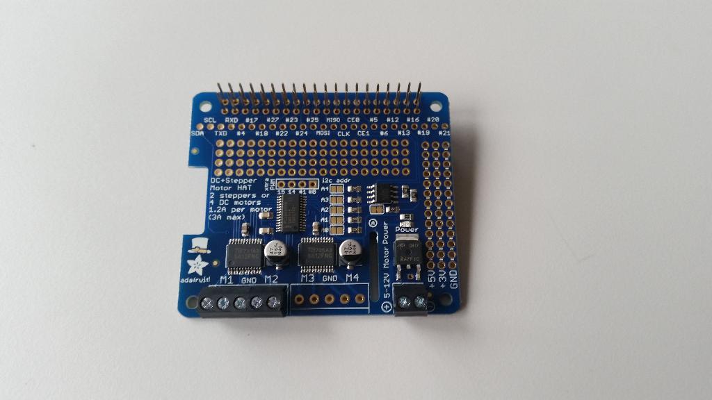
Soldered DC Motor HAT
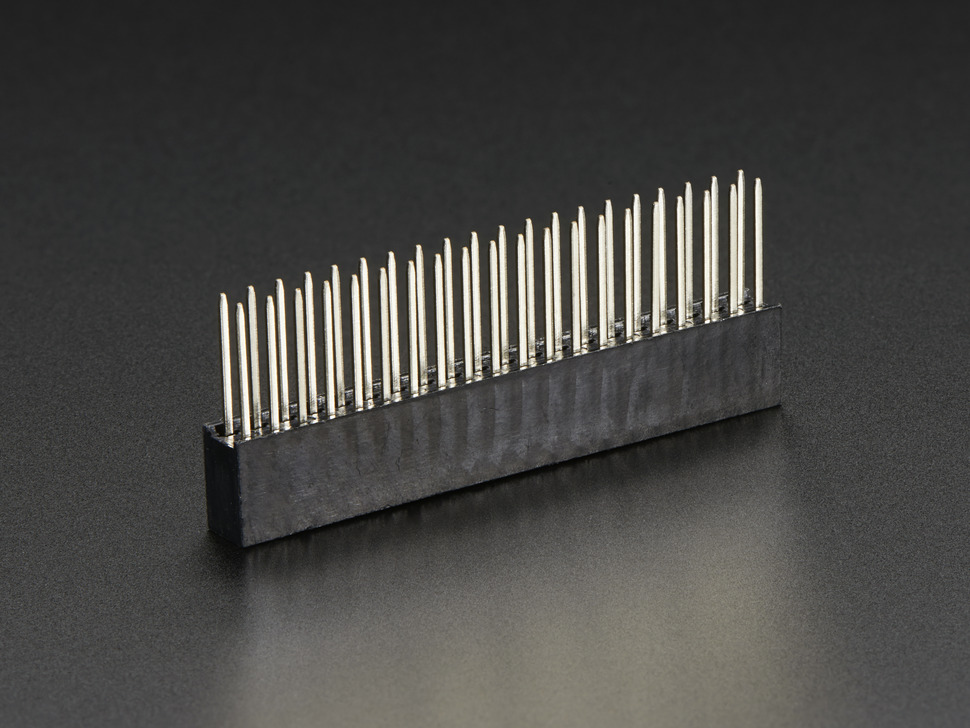
Preparing the components
✎Take the GPIO stacking header Figure 16.52 out of Duckiebox and sort the following components from DC motor HAT package:
-
Adafruit DC/Stepper Motor HAT for Raspberry Pi
-
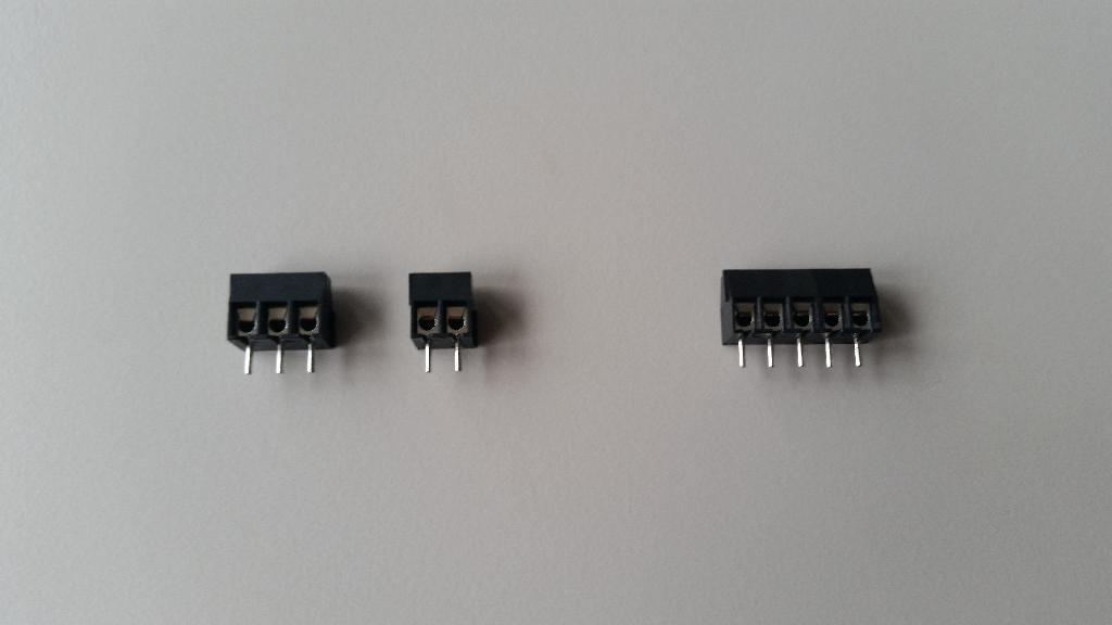
2-pin terminal block (2x), 3-pin terminal block (1x)

Soldering instructions
✎1) Make a 5 pin terminal block by sliding the included 2 pin and 3 pin terminal blocks into each other Figure 16.54.
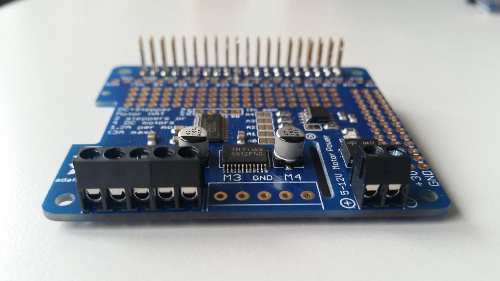
2) Slide this 5 pin block through the holes just under “M1 GND M2” on the board. Solder it on (we only use two motors and do not need connect anything at the “M3 GND M4” location) (Figure 16.57);
3) Slide a 2 pin terminal block into the corner for power. Solder it on. (Figure 16.56);
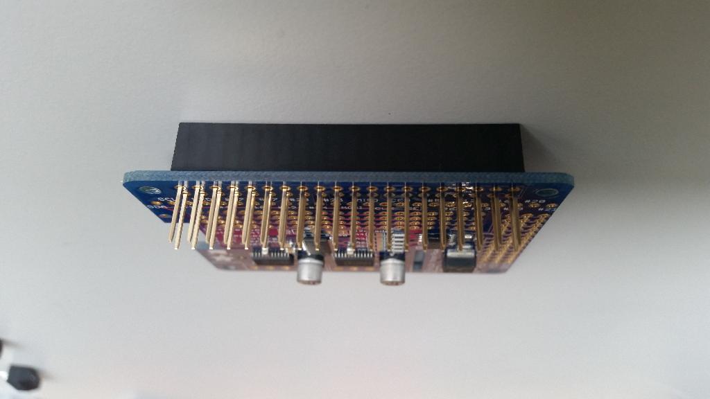
4) Slide in the GPIO Stacking Header onto the 2x20 grid of holes on the edge opposite the terminal blocks and with vice versa direction (Figure 16.55). Solder it on.
stick the GPIO Stacking Header from bottom to top, different orientation than terminal blocks (from top to bottom).
Assembly instructions (DB17-l): soldering the PWM / Servo HAT and LED boards
✎
Modified 2021-03-13 by duckietown
Duckiebot DB17-l parts. The acquisition process is explained in Subsection 3.2.1 - DB17 Bill of materials.
The configurations are described in Unit B-2 - Duckiebot Configurations. In particular you need:
Time: 30 minutes
A soldered PWM / Servo HAT for DB17-l configuration.
16-channel PWM/Servo HAT
✎(Alternative instructions: how to solder on the PWM/Servo HAT)
Prepare the components
✎Put the following components on the table according the Figure
- GPIO Stacking Header for A+/B+/Pi 2
- Adafruit HAT Mini Kit of 16-Channel PWM / Servo HAT for Raspberry Pi
- 3x4 headers (4x)
- 2-pin terminal block
- 16-Channel PWM / Servo HAT for Raspberry Pi (1x)
- LED HAT

PWM / Servo HAT soldering instructions
✎Modified 2021-03-13 by duckietown
- Solder the 2 pin terminal block next to the power cable jack
- Solder the four 3x4 headers onto the edge of the HAT, below the words “Servo/PWM Pi HAT!”
- Solder the GPIO Stacking Header at the top of the board, where the 2x20 grid of holes is located.
LSD board soldering instructions
✎Modified 2021-03-13 by duckietown
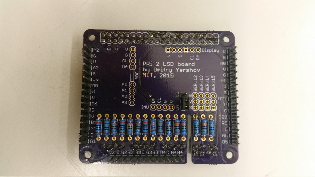
The LSD board you received is unpopulated and should look like this:

Prepare the components
✎Put the following components according the figure on the table:
- 1 x 40 pin female header
- 5 x 4 pin female header
- 2 x 16 pin male header
- 1 x 12 pin male header
- 1 x 3 pin male header
- 1 x 2 pin female shunt jumper
- 5 x 200 Ohm resistors
- 10 x 130 Ohm resistors
- 3 x 4 pin male header for servos

Soldering instructions
✎- Put the resistors on the top of the board according to silkscreen markings, solder it on from the bottom side.
Tips:
-
Solder all female headers to the bottom of the board. Alignment becomes easy if the female headers are plugged into the PWM heat, and the LSD board rests on top.
-
Solder all male headers to the top of the board. Male header positions are outlined on the silkscreen.
LED connection
✎
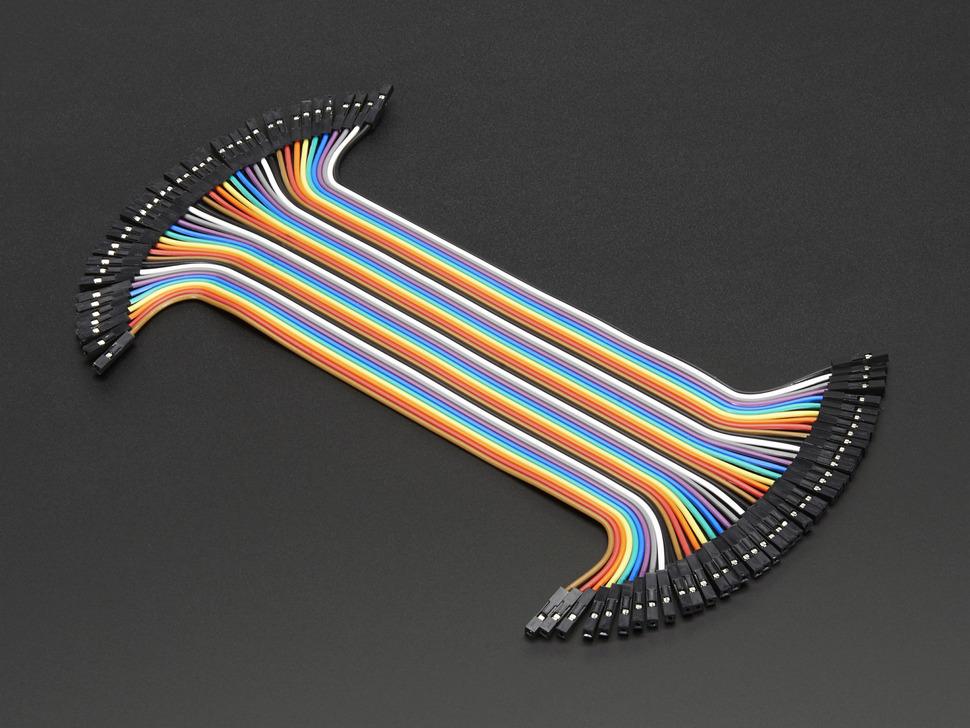
Parts list:
- 4 x 6” female-female jumper cable
Instructions:
-
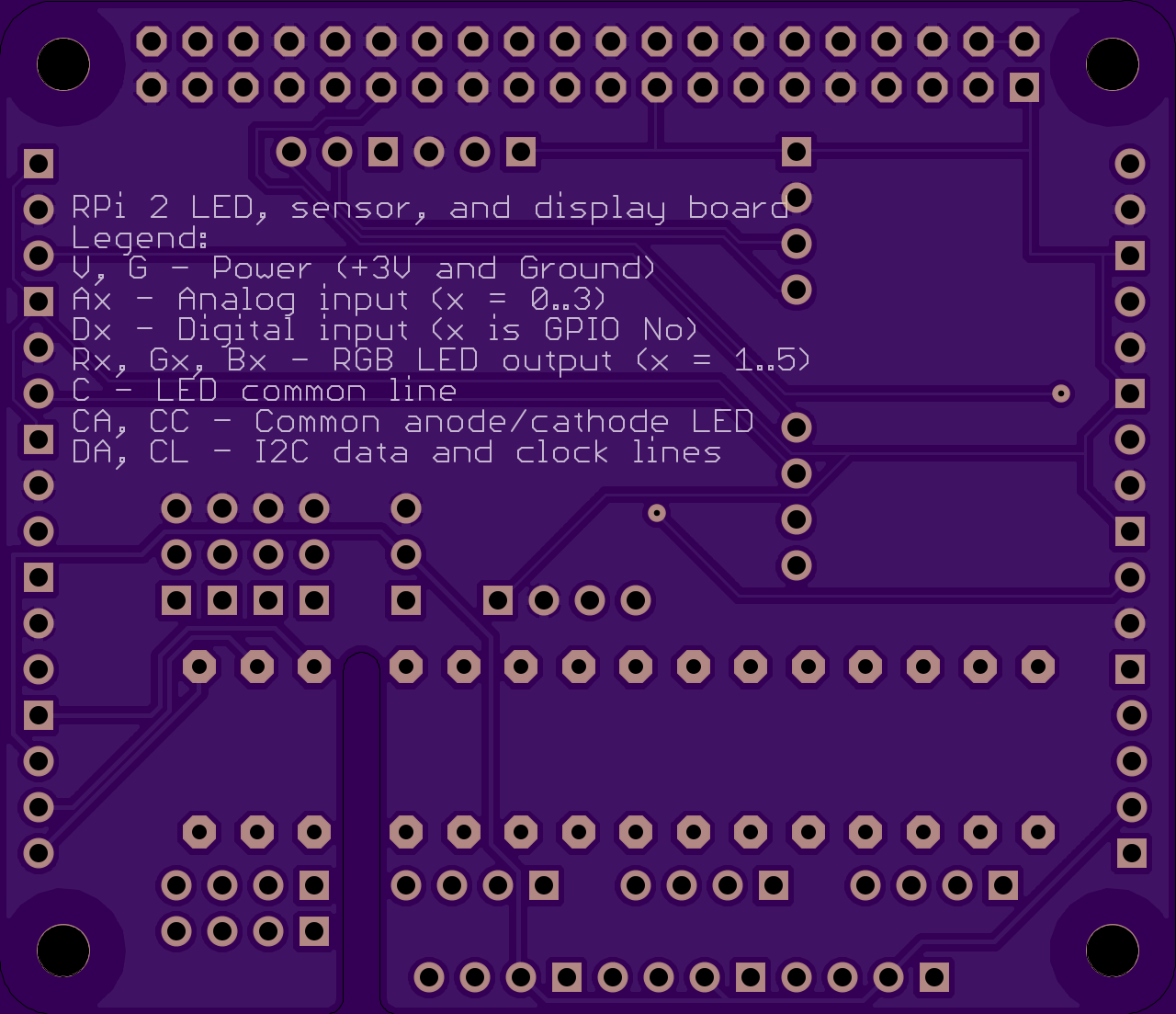
Connect LED accordingly to silkscreen indication on PRi 2 LSD board
-
silkscreen legend: Rx, Gx, Bx are red, green, and blue channels, accordingly, where x is the LED number; C is a common line (either common anode or common cathode)
-
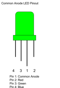
For adafruit LEDs are common anode type. The longest pin is common anode. Single pin on the side of common is red channel. The two other pins are Green and Blue channels, with the blue furthest from the common pin.
-
Both types of LEDs are supported. Use shunt jumper to select either common anode (CA) or common cathode (CC) on 3-pin male header. Note, however, that all LEDs on the board must be of the same type.
Putting things together
✎-
Stack the boards
-
Screw the first eight standoffs into the Pi - provide hints on the location of standoffs and the suggested orientation of the boards w/r to the chassis
-
connect the camera to the Pi [image showing the connector ?]
-
Stack the DC/Stepper Motor HAT onto the Pi, aligning both sets of GPIO pins over each other and screw the standoffs to secure it. Try to not bend the camera connector too much during this step
-
Stack the 16-channel PWM/Servo HAT onto the Pi, both sets of GPIO pins over each other and screw the standoffs to secure it
-
-
Slide the battery between the two chassis plates
-
Power the PWM/Servo HAT and Pi connecting them to the battery with the cables included in the duckiebox
-
Power the DC/Stepper motor from the PWM/Servo HAT using the male-to-male cable in the duckiebox, connect the positive
-
connect the Pi to the board
-
Done!
Assembly instructions (DB17-jwd): power cable
✎
Modified 2021-03-13 by duckietown
In configuration DB17 we will need a cable to power the DC motor HAT from the battery. The keen observer might have noticed that such a cable was not included in the DB17 Duckiebot parts chapter. Here, we create this cable by splitting open any USB-A cable, identifying and stripping the power wires, and using them to power the DC motor HAT. If you are unsure about the definitions of the different Duckiebot configurations, read Unit B-2 - Duckiebot Configurations.
It is important to note that these instructions are relevant only for assembling a DB17-wjdc configuration Duckiebot (or any subset of it). If you intend to build a DB17-l configuration Duckiebot, you can skip these instructions.
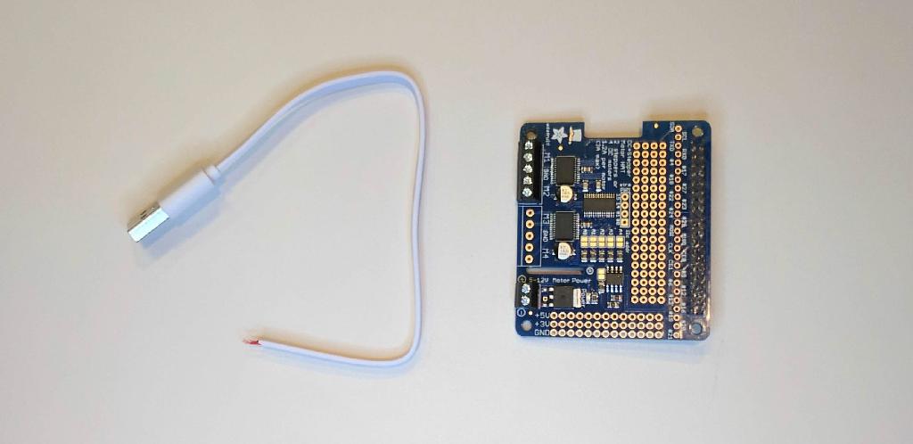
One male USB-A to anything cable.
A pair of scissors.
A multimeter (only if you are not purchasing the suggested components)
Time: 5 minutes
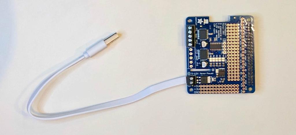
One male USB-A to wires power cable
Video tutorial
✎The following video shows how to prepare the USB power cable for the configuration DB17.

The video is at https://vimeo.com/236334476.
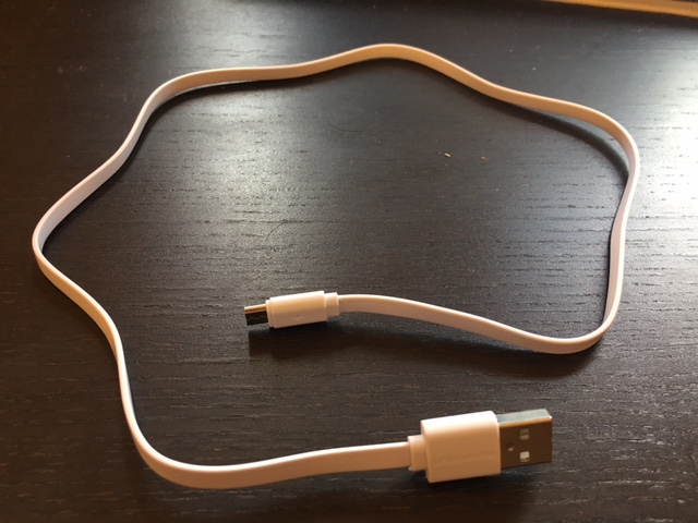
Step 1: Find a cable
✎To begin with, find a male USB-A to anything cable.
If you have purchased the suggested components listed in Unit B-3 - Getting the Duckiebot hardware, you can use the longer USB cable contained inside the battery package (Figure 16.61), which will be used as an example in these instructions.

Put the shorter cable back in the box, and open the longer cable (Figure 16.62)
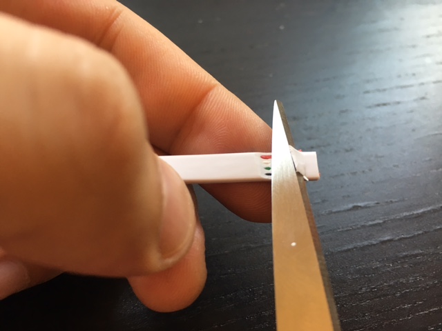
Step 2: Cut the cable
✎Make sure the USB cable is unplugged from any power source before proceeding.
Take the scissors and cut it (Figure 16.63) at the desired length from the USB-A port.
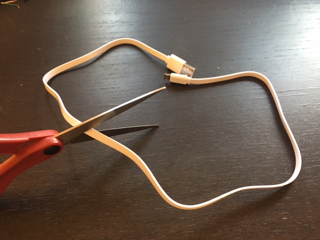
The cut will look like in Figure 16.64.

Step 3: Strip the cable
✎Paying attention not to get hurt, strip the external white plastic. A way to do so without damaging the wires is shown in Figure 16.65.
After removing the external plastic, you will see four wires: black, green, white and red (Figure 16.66).
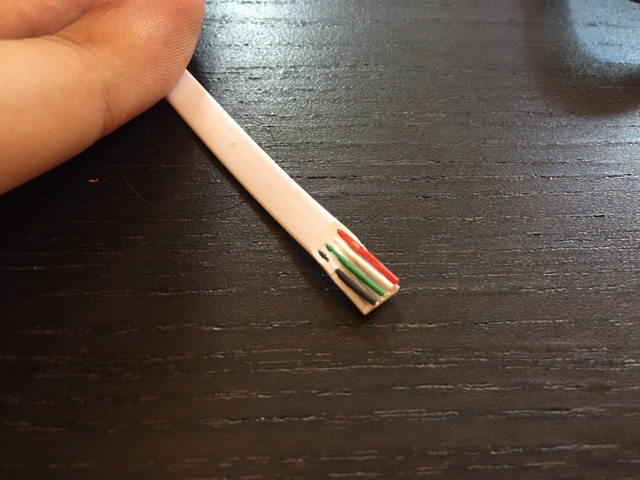
Once the bottom part of the external cable is removed, you will have isolated the four wires (Figure 16.67).

Step 4: Strip the wires
✎Make sure the USB cable is unplugged from any power source before proceeding.
Once you have isolated the wires, strip them, and use the scissors to cut off the data wires (green and white, central positions) (Figure 16.68).
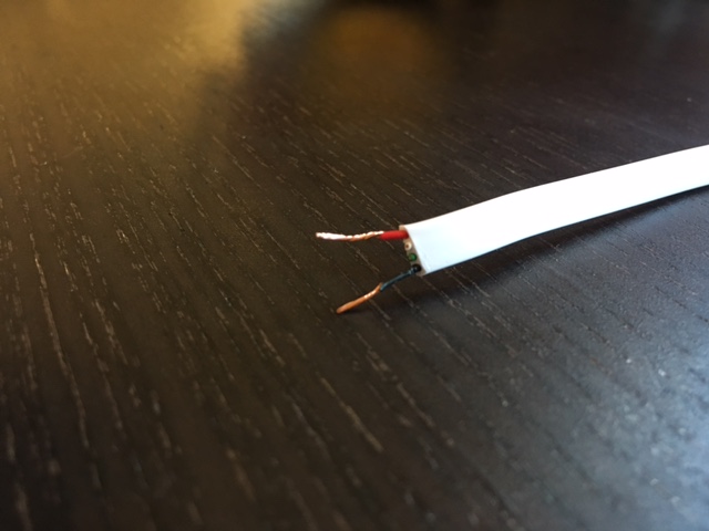
If you are not using the suggested cable, or want to verify which are the data and power wires, continue reading.
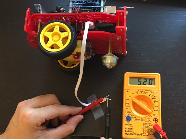
Step 5: Find the power wires
✎If you are using the USB-A cable from the suggested battery pack, black and red are the power wires and green and white are instead for data.
If you are using a different USB cable, or are curious to verify that black and red actually are the power cables, take a multimeter and continue reading.
Plug the USB port inside a power source, e.g., the Duckiebot’s battery. You can use some scotch tape to keep the cable from moving while probing the different pairs of wires with a multimeter. The voltage across the pair of power cables will be roughly twice the voltage between a power and data cable. The pair of data cables will have no voltage differential across them. If you are using the suggested Duckiebot battery as power source, you will measure around 5V across the power cables (Figure 16.69).
Step 6: Test correct operation
✎You are now ready to secure the power wires to the DC motor HAT power pins. To do so though, you need to have soldered the boards first. If you have not done so yet, read Section 16.2 - Assembly instructions (DB17): soldering.
If you have soldered the boards already, you may test correct functionality of the newly crafted cable. Connect the battery with the DC motor HAT by making sure you plug the black wire in the pin labeled with a minus: - and the red wire to the plus: + (Figure 16.70).

Bumper Assembly
✎Modified 2021-03-13 by duckietown
Duckiebot DB17-lc parts.
Having the Duckiebot with configuration DB17-wjd assembled. The assembly process is explained in Section 16.1 - Assembly instructions (DB17-jwd).
Time: about 15 minutes.
A Duckiebot with Bumpers (configuration DB17-l2)
Locate all required parts
✎Modified 2021-03-13 by duckietown
The following should be included in your parts envelope (See image below for these components):
- 1x front bumper (Camera side)
- 1x rear bumper (the side of Caster/Omnidirectional wheel)
- 2x rear bumper brace (the side of Caster/Omnidirectional wheel)
- 8x M2.5x10 nylon or metal screws
- 8x M2.5 nuts
The following is not included in your parts envelope but will be needed for assembly:
- Small screwdriver


Reminder: Use care when assembling!
✎Modified 2021-03-13 by duckietown
Use care when assembling, make sure to be gentle! Tighten screws just enough so that the parts will remain stationary. When inserting LEDs, gently work them into their holders. While the acrylic is relatively tough, it can be fractured with modest force. We don’t have many replacements (at this moment) so we may not be able to replace a broken part.
Remove protective paper
✎Peel protective layer off of all parts on all sides.
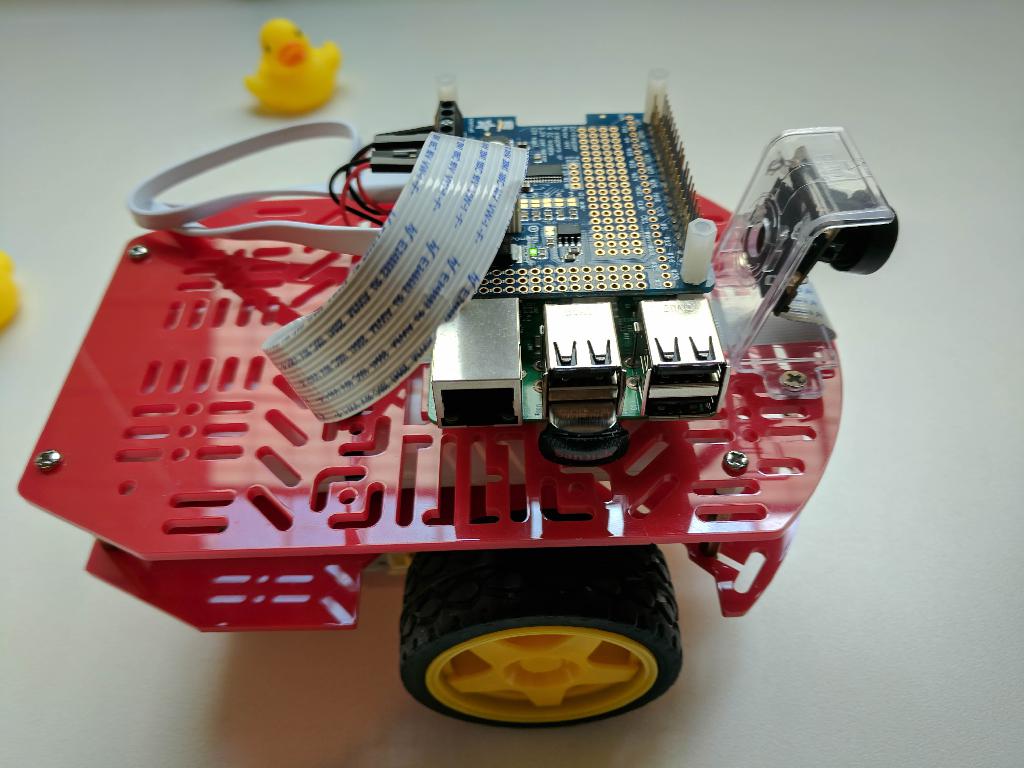
Assembly Rear Spacers
✎Modified 2021-03-13 by duckietown
Disassembly the spacers between the both chassis
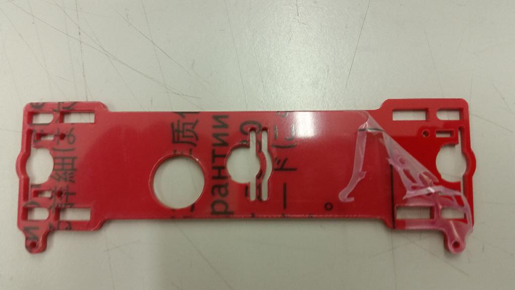
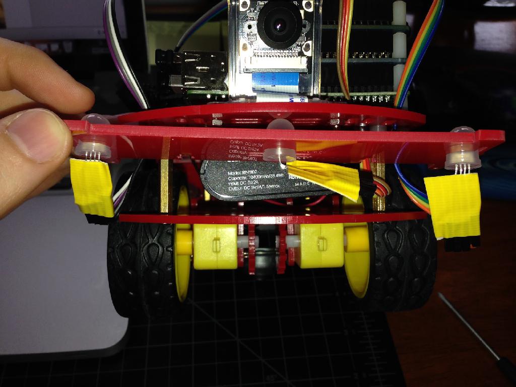
✎The backside of duckiebot before assemblying the bumpers looks as Figure 16.74:
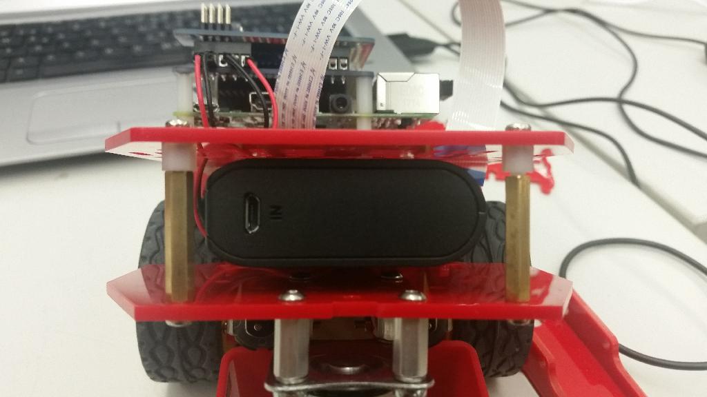
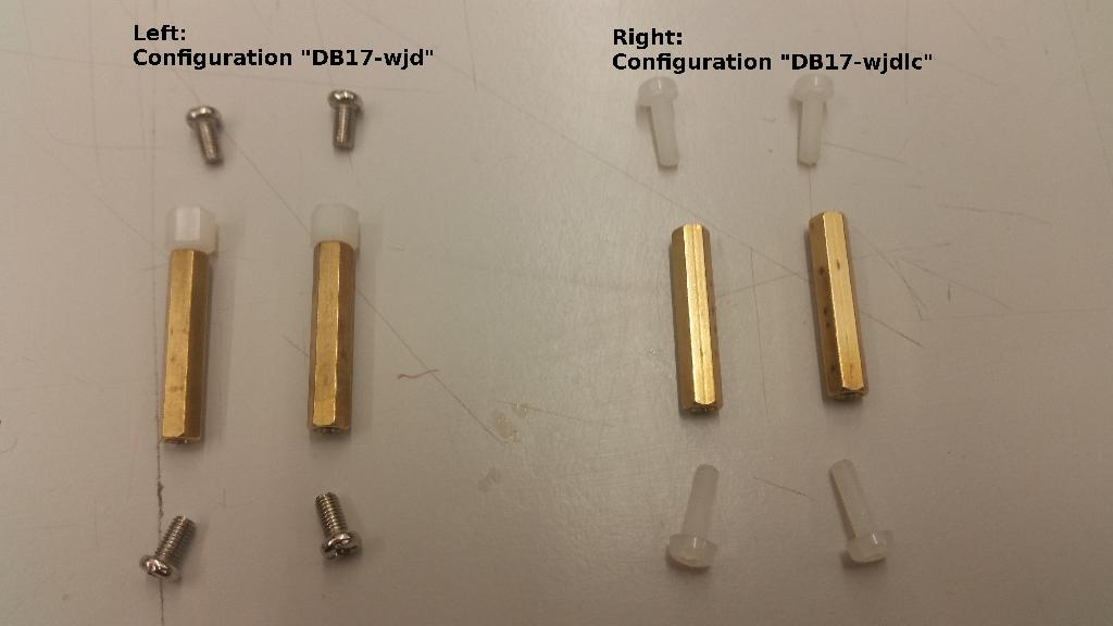
Now remove the spacers and the (short)metall screws from the standoffs (configuration ‘DB17-wjd’) and replace it with 4 M3x10 nylon screws for connecting the chassis and the bumper spacers.
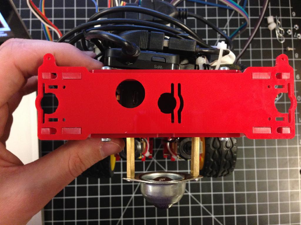
M3x10 screws attaching bottom rear brace:

Back View, fully assembled:

For the ETH students, the M3*10 nylon screws for attaching the rear spacers with chassis were already distributed during the duckiebot ceremony and not included in second distribution. Please reuse them!
Mount Rear Bumper
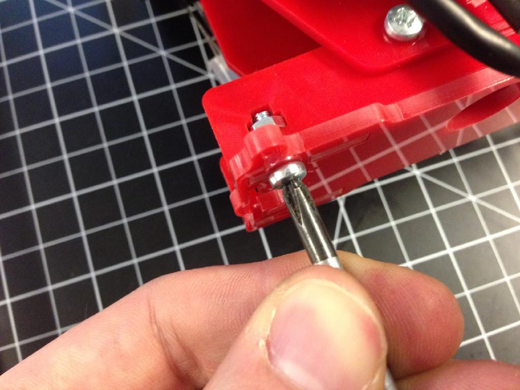
✎Carefully guide rear bumper on to rear bumper brace tabs. Ensure that the hole for charging aligns with the charging port on your battery.
Locate 4 M2.5 nylon/metall nuts and 4 M2.5*10 nylon screws. Place a nut in the wide part of the t-slot and thread a screw into the nut as shown in the following pictures. Note Use care when assembling! If you are having trouble with the nuts falling out, take a small piece of transparent tape and place it over both sides of the t-slot with the nut inside. It won’t look as nice but it will be much easier to assemble.
Test the screws and the nuts once by screwing them together before you use it for the bumpers. It make the fllowing assembly process much easier.
For ETH 2017, the screws and nuts using for this step are M2.5*10 nylon screws (white) and M2.5 nylon or metall nuts from the envelope.
The completed rear bumper should look like this:

Congrats! your rear bumper assembly is complete!
Mount Front Bumper
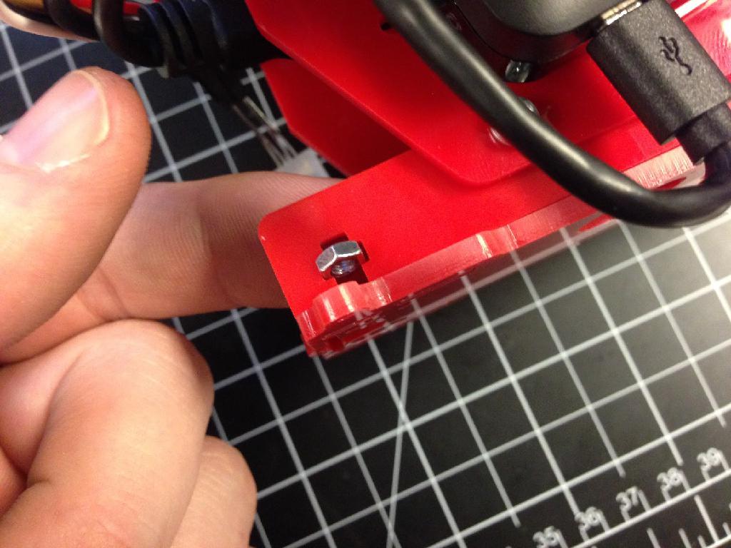
✎The front side of Duckiebot in DB17-wjd should look like in Figure 16.82.
Take 2x M2.5*10 nylon screws and 2x M2.5 nylon nuts and install them as shown in the following pictures. The first picture shows the correct holes to mount these screws (The correct position is the widest pair of 3mm holes beside the camera). The nuts should tightened on by a few threads (these are the two nuts that are not yet tightened at the top of the second picture):

Before tighten the front bumper, you should organize the wires of LEDs going through the right holes of chassis. The center LED should be bent at a right angle in the direction that the wire is fed through the body.
Take the front bumper and carefully press the LEDs into the bumper holders. Take care that the wires are routed behind the front bumper. Also note that the front center LED wire should not be crushed between the bumper and the right spacer (you will likely fracture the bumper if you try to force it). The center LED should be bent at a right angle in the direction that the wire is fed through the body (see Figure 16.83).
Position the bumper so that the nuts align with the t-slots. You may need to loosen or tigthen the screws to align the nuts. You may also need to angle the front bumper when inserting to get it past the camera screws.

Gently tighten the nuts. The front bumper should now stay in position.
Assembly instructions (DB17-l)
✎
Modified 2021-03-13 by duckietown
Duckiebot DB17-lc parts. The acquisition process is explained in Subsection 3.2.1 - DB17 Bill of materials.
Soldering DB17-lc parts. The soldering process is explained in Section 16.2 - Assembly instructions (DB17): soldering.
Having assembled the Duckiebot in configuration DB17 (or any DB17-wjd). The assembly process is explained in Section 16.1 - Assembly instructions (DB17-jwd).
Time: about 30 minutes.
An assembled Duckiebot in configuration DB17-wjdlc.
Assembly the Servo/PWM hat (DB17-l1)
✎
Modified 2021-03-13 by duckietown
Recommend: If you have bumpers, it is recommend to have them assembled before the PWM hat. The assembly process is explained in Section 16.3 - Bumper Assembly.
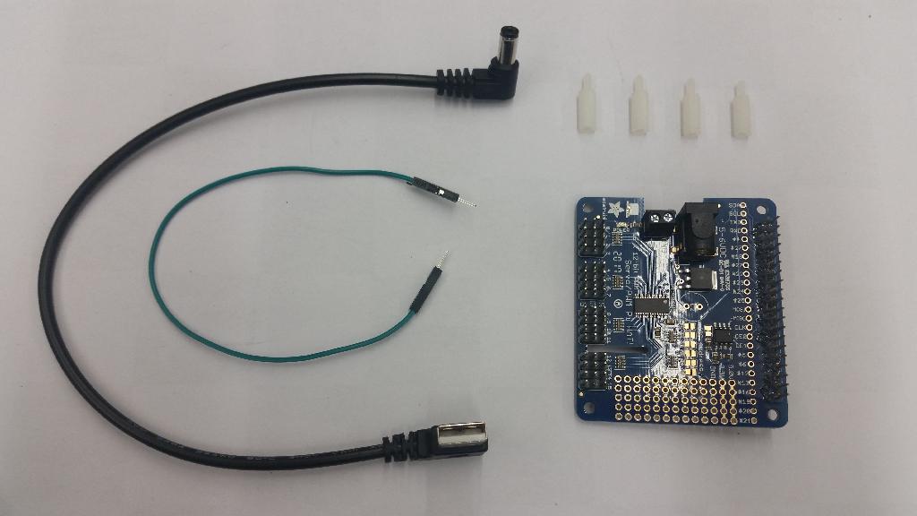
Locate the components for Servo/PWM hat
✎- Soldered PWM hat (1x)
- Nylon Standoffs (M3.5 12mm F-F) (4x)
- Power cable: short angled male USB-A to 5.5/2.1mm DC power jack cable
- Male-Male Jumper Wires (1x)
- Screwdriver
Remove the hand-made USB power cable from DC Motor HAT
✎From now on, the DC Motor Hat will be powered by the PWM HAT via male -male jumper wire. Before that, the previous hand-made USB power cable needed to be removed. Insert the male-male jumper wire into + power terminal on the DC motor HAT (DC-end).
Stack the PWM HAT above the DC motor HAT
✎Put a soldered Servo/PWM HAT board (in your Duckiebox) with 4 standoffs on the top of Stepper Motor HAT.
Insert the other end of male-male jumper wire into “+5“V power terminal on the PWM HAT (PWM-end). It leads the power to DC motor HAT.

Power Supply for PWM HAT
✎To power the PWM/Servo HAT from the battery, plugin a short (30cm) angled male USB-A to 5.5/2.1mm DC power jack cable into PWM HAT. The other end of the power cable will plugin to the battery when it is in use.
Assembling the Bumper Set (DB17-l2)
✎
Modified 2021-03-13 by duckietown
For instructions on how to assemble your bumpers set, refer to: Section 16.3 - Bumper Assembly.
Assembling the LED HAT and LEDs (DB17-l3)
✎
Modified 2021-03-13 by duckietown
For instructions on how to assemble the LED HAT and related LEDs, refer to: Section 16.5 - Assembling the DB17-lc.
Assembling the DB17-lc
✎
Modified 2021-03-13 by duckietown
Duckiebot DB17-lc parts.
The acquisition process is explained in Section 3.2 - Acquiring the parts for a DB17.
Soldering DB17-lc parts.
The soldering process is explained in Section 16.2 - Assembly instructions (DB17): soldering.
Having assembled PWM Hat on the Duckiebot with configuration DB17-wjd. The assembly process is explained in Unit C-16 - Assembly - Duckiebot DB17.
Time: about 15 minutes.
A Duckiebot with LEDs attached and functioning (configuration DB17-l3)
Locate all required parts
✎To attach the LEDs on the Duckiebots, the following components are needed:
- Soldered LSD board with Jumper
- LED (5x)
- Female-female wires (20x)
- Nylon standoffs M2.5*12
- some Tape

Connecting Wires to LEDs
✎Modified 2021-03-13 by duckietown
LEDs
✎The LEDs are common anode type. The longest pin is called the common. The single pin on the side of common is red channel. The two other pins are Green and Blue channels, with the blue furthest from the common pin.
Use the long wires with two female ends. Attach one to each of the pins on the LED.
To figure out the order to connect them to the LSD hat, use the legend on the silkscreen and the information above. i.e. RX - means the red pin, CX - means the common, GX means the green, and BX means the blue. The “X” varies in number from 1-5 depending on which LED is being connected as discussed in the next section.
Use Tape to keep the LEDs stick with the wires.
Connecting LEDs to LSD Hat
✎Modified 2021-03-13 by duckietown
Silkscreen legend: Rx, Gx, Bx are red, green, and blue channels, accordingly, where x is the LED number; C is a common line (either common anode or common cathode).
Define the following names for the lights:
- “top” = top light - the “top” light is now at the bottom
- fl = front left
- fr = front right
- br = back right
- bl = back left
The LEDs are wired according to Figure 16.92.

Mappings from the numbers on the LED hats to the positions shown (TOP is now the one in the middle at the front)
- FR -> 5
- BR -> 4
- TOP -> 3
- BL -> 2
- FL -> 1
Running the Wires Through the Chassis
✎Modified 2021-03-13 by duckietown
It is advised that the LED cables are routed through the positions noted in the images below before installing the bumpers:
Front Left, Front Middle, and Front Right LED Wiring suggestion:

Final tweaks
✎Modified 2021-03-13 by duckietown
Adjust the LED terminals (particularly in the front) so that they do not interfere with the wheels. This can be accomplished by bending them up, away from the treads.